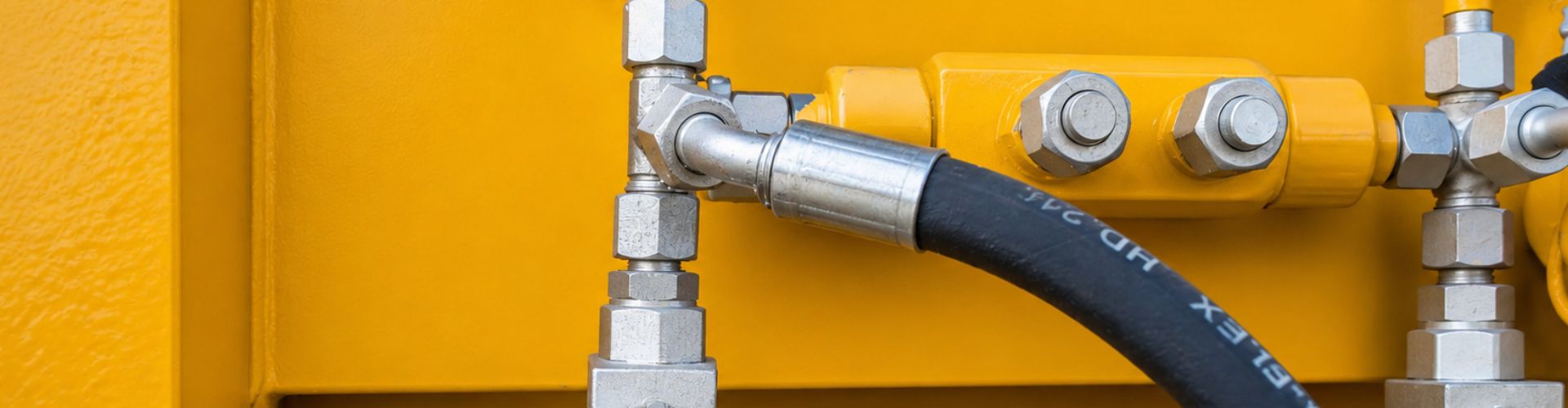
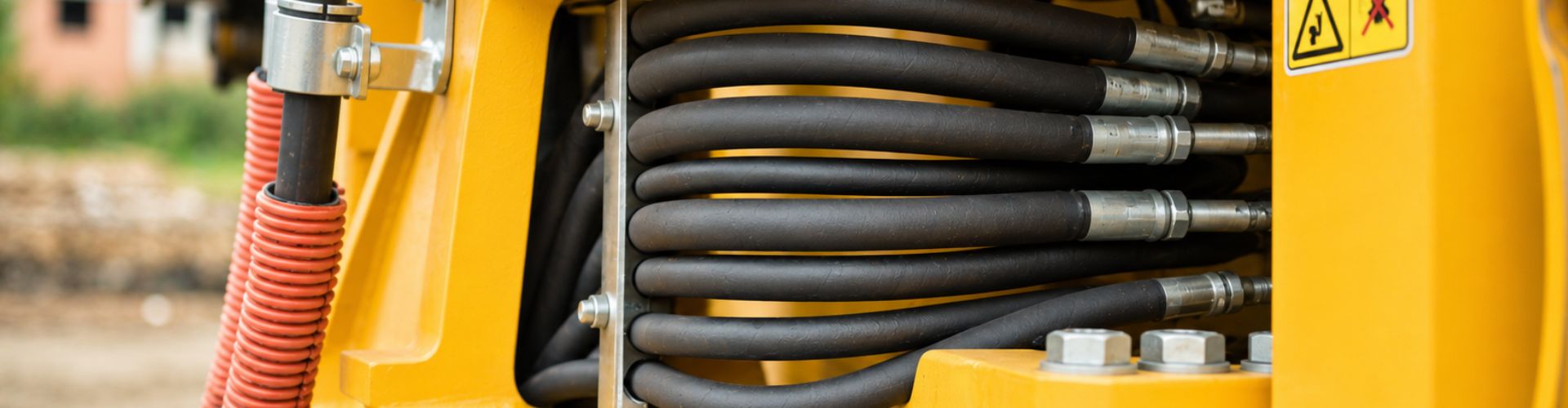
Why Do Hydraulic Hoses Fail in Cold Weather?
Hydraulic hoses fail in cold weather because low temperatures cause
Hydraulic hoses fail in cold weather because low temperatures cause
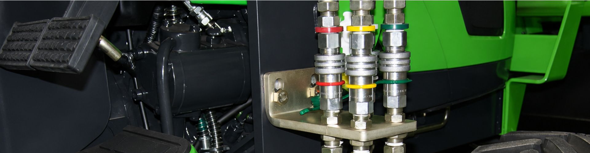
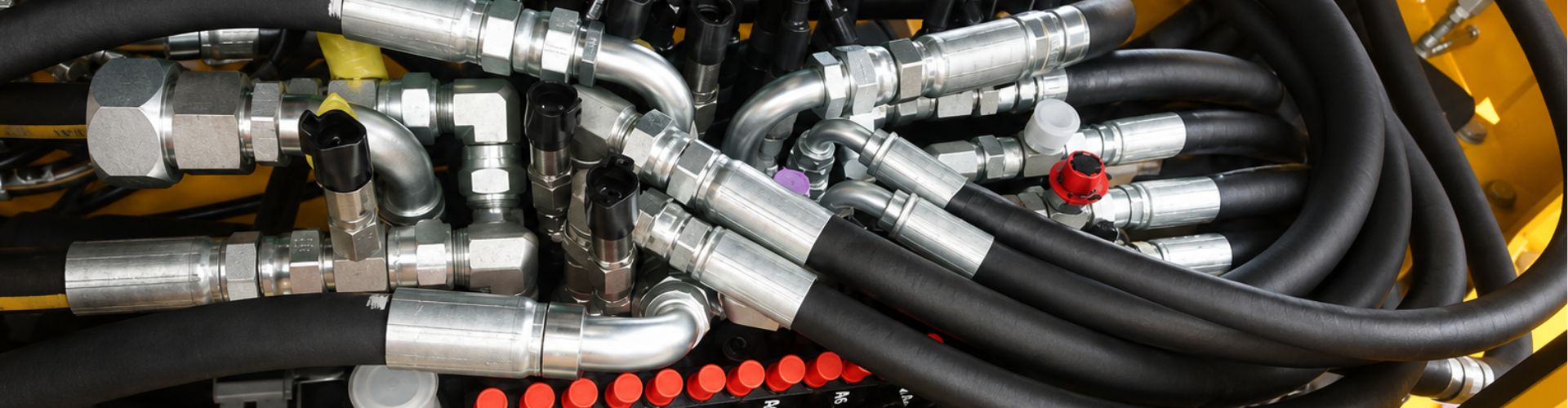
Quick couplings fail under heavy pressure primarily due to localized
You are operating a heavy-duty front-end loader during peak harvest
Hydraulic fittings fail during installation primarily due to excessive torque,
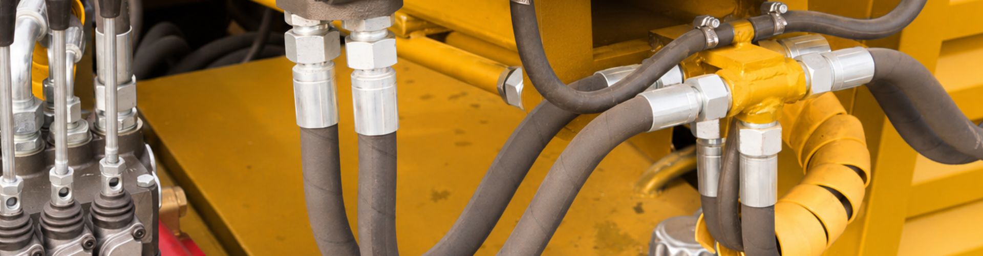
Improper hydraulic hose routing drastically shortens hydraulic cylinder life by
You are standing next to an industrial machine during a
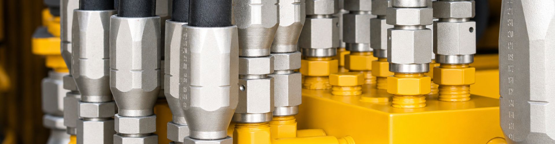
Identifying the correct thread and seat combination requires direct physical
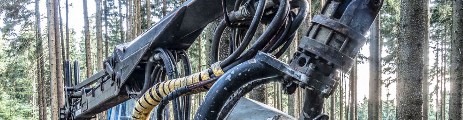
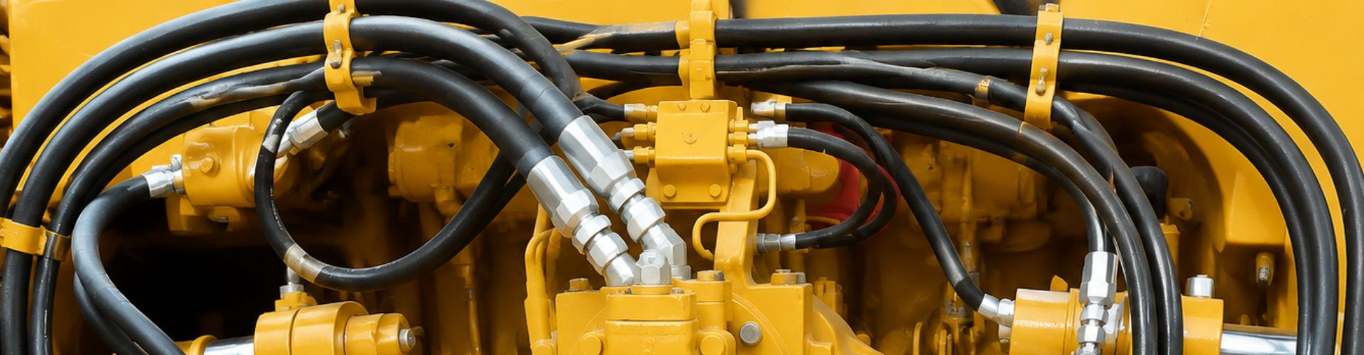
Hydraulic hose problems in forestry machinery are primarily caused by
Hydraulic cylinder failure is directly caused by a loss of
Imagine you are standing next to an industrial tractor during