Why Hydraulic Cylinder Fail Starts With Port Restriction?
You are operating your heavy agricultural tractor or loader during
You are operating your heavy agricultural tractor or loader during
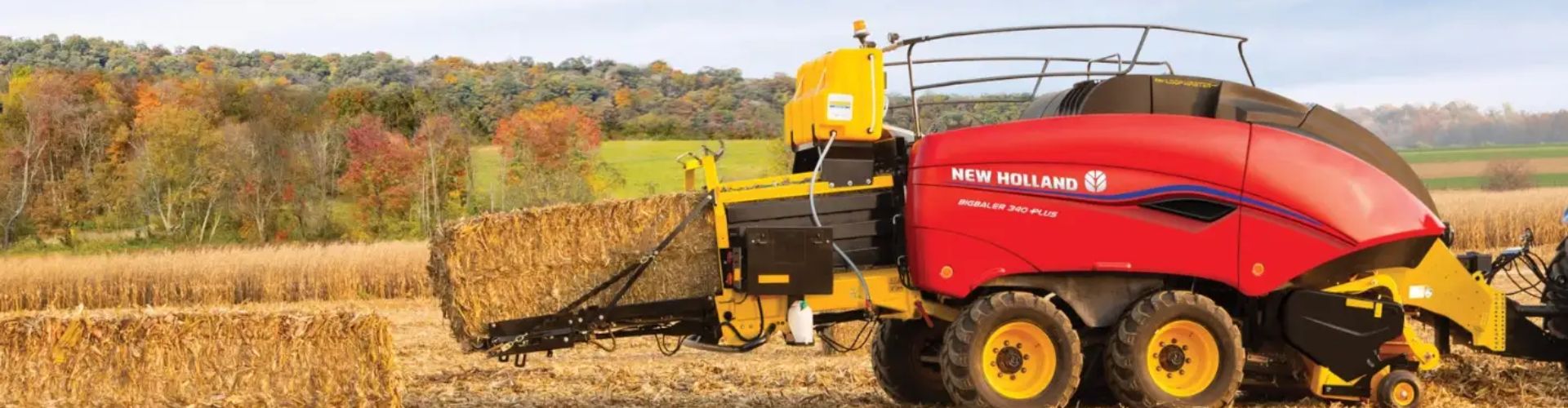
Tractor lift cylinders fail during peak working seasons due to
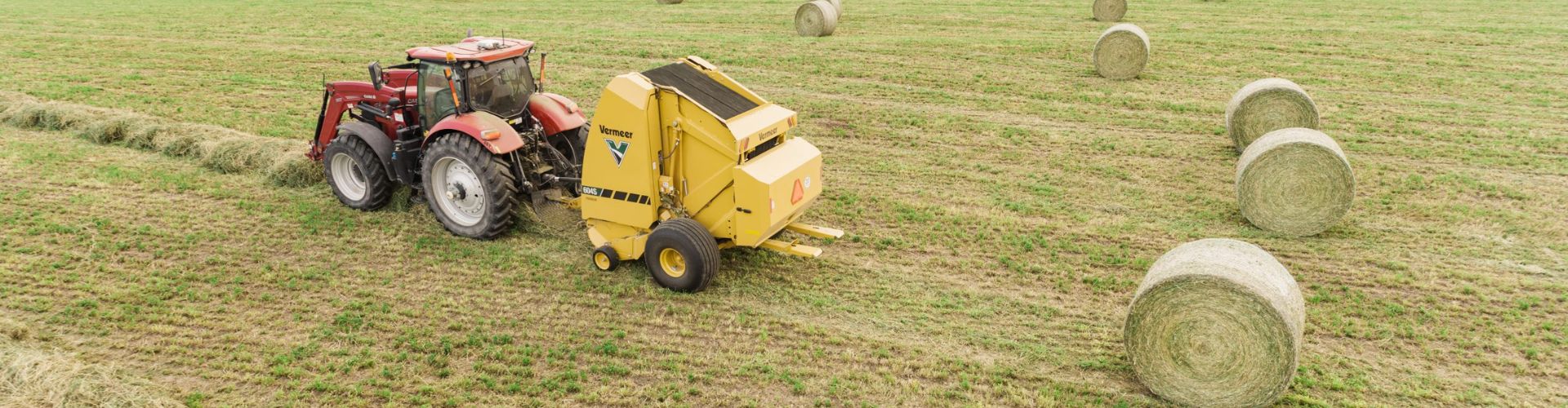
Plugging shocks damage baler tailgate cylinders because the sudden, massive
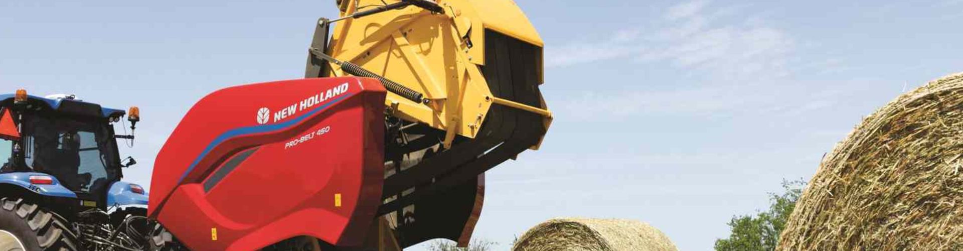
Door twist starts from uneven tailgate hydraulic cylinders when one
Imagine operating your agricultural or waste management equipment during a
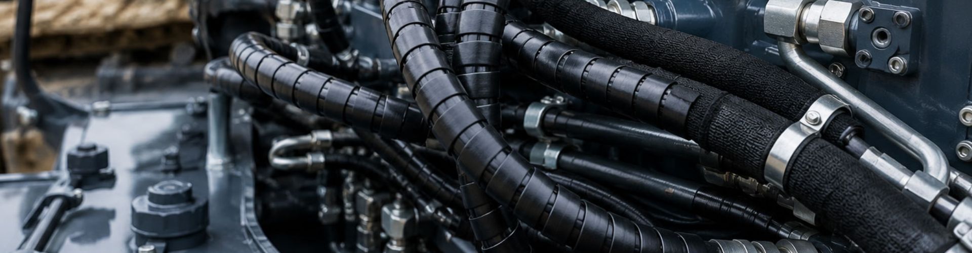
Hydraulic hose failures directly destabilize agricultural fleets by causing immediate
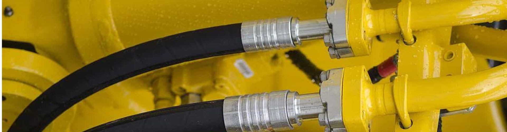
Matching hydraulic fittings for older tractors requires identifying the specific
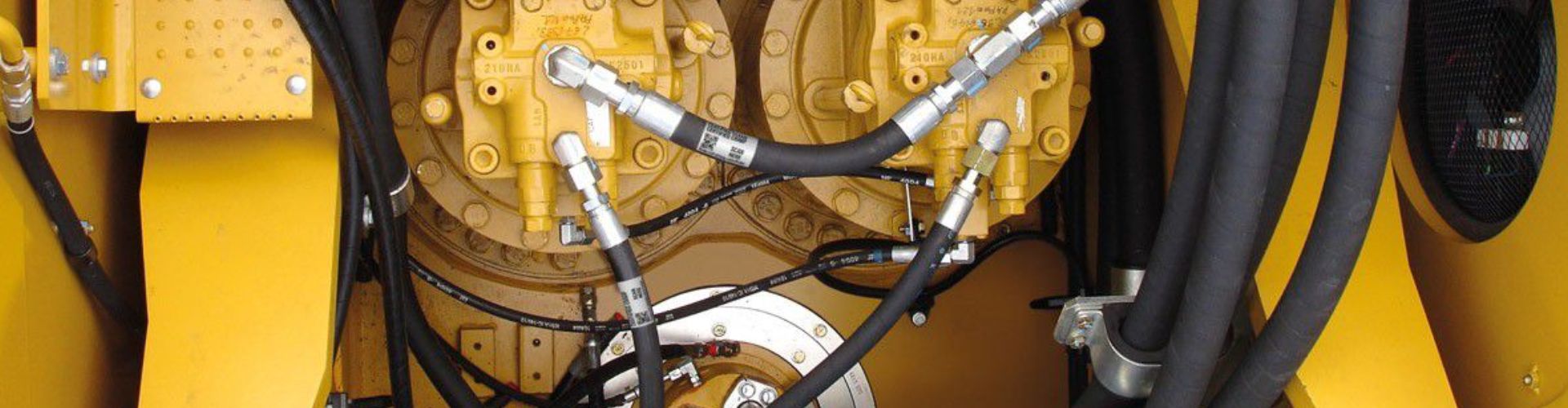
Excavator hydraulic hoses fail during hot weather servicing primarily due
The reason your excavator hose repairs fail repeatedly is usually
Imagine a high-capacity forklift mid-shift in a busy distribution center.