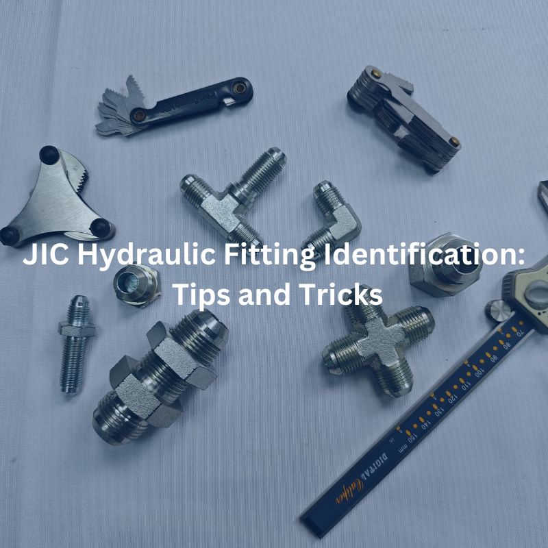
Understanding JIC Fitting Measurements Basic Tips and Errors

JIC Fitting Measurements: Basic Tips and Errors

JIC Fitting Measurements: Basic Tips and Errors

Table of Contents

Introduction

JIC hydraulic fittings are crucial components in hydraulic systems, ensuring leak-proof connections and efficient fluid flow. This post aims to provide essential tips for accurately measuring JIC fittings and highlight common errors that can compromise system performance. Understanding these measurements is vital for maintaining safety, reliability, and efficiency in various industrial applications.

What are JIC Fittings?

JIC (Joint Industry Council) fittings are integral components in various hydraulic systems, known for their reliability and durability. These fittings are standardized by the SAE (Society of Automotive Engineers), which ensures a consistent and high-quality product across different manufacturers and applications.

Key Characteristics of JIC Fittings

37-Degree Flare Seating Surface:

The defining feature of JIC fittings is their 37-degree flare. This design facilitates a robust metal-to-metal seal, which is crucial for preventing leaks under high-pressure conditions. The flare connection also allows for easy assembly and disassembly, making maintenance more straightforward.

Standardization:

The standardization by SAE means that JIC fittings have uniform specifications, allowing for interchangeability and compatibility across different brands and systems. This consistency is particularly important in industries where precision and reliability are paramount.

Understanding JIC Fitting Measurements

Accurate measurement of JIC fittings is essential to ensure proper fit and function. The primary parameters to consider are thread size, thread pitch, outside diameter (OD), and inside diameter (ID).

Thread Size:

  • Definition: Thread size refers to the nominal size of the threads on the fitting.
  • Importance: Correctly identifying the thread size ensures compatibility with corresponding components. Using the wrong thread size can lead to improper sealing and potential system failure.

Thread Pitch:

  • Definition: Thread pitch is the distance between threads, typically measured in threads per inch (TPI).
  • Measurement: To measure thread pitch, use a thread gauge, which helps determine the number of threads per inch. Accurate pitch measurement is critical for matching the fitting with the correct mating component.
  • Importance: Proper thread pitch ensures a secure and tight connection, preventing leaks and maintaining system integrity.

Outside Diameter (OD):

  • Definition: The outside diameter is the external width of the fitting’s threaded section.
  • Measurement: Use calipers to measure the OD accurately. Place the calipers around the threaded section, ensuring they are perpendicular to the fitting.
  • Importance: Accurate OD measurement is essential for ensuring that the fitting fits properly within the hydraulic system. An incorrect OD can cause fitting misalignment and leaks.

Inside Diameter (ID):

  • Definition: The inside diameter is the internal width of the fitting, determining the flow capacity.
  • Measurement: Measure the ID using calipers. Insert the calipers inside the fitting’s opening and expand them until they touch the internal walls.
  • Importance: Correct ID measurement ensures that the fitting allows the proper flow of hydraulic fluid. An incorrect ID can restrict flow, reducing system efficiency and causing potential damage.

Step-by-Step Guide to Measuring JIC Fittings

Accurate measurement of JIC fittings is critical for ensuring proper fit and function in hydraulic systems. Follow these detailed steps to achieve precise measurements:

Measure Thread Size and Pitch

length measure Topa

Use a Thread Gauge:

  • Select the Appropriate Gauge: Choose a thread gauge that matches the size range of the fitting you are measuring.
  • Align the Gauge: Hold the fitting firmly and align the thread gauge with the threads of the fitting. Ensure that the gauge fits snugly into the threads without forcing it.

Check for a Snug Fit:

  • Visual Inspection: Once the gauge is in place, visually inspect the fit. The threads of the gauge should align perfectly with the threads of the fitting.
  • Feel for Fit: Gently move the gauge back and forth. A proper fit will feel smooth without any wobbling or gaps.

Record the Thread Size and Pitch:

  • Documentation: Note down the thread size (e.g., 7/16-20) and the pitch (threads per inch, TPI). Accurate documentation is essential for matching the fitting with corresponding components.

Measure the Outside Diameter (OD)

Place the Calipers Around the Threaded Section:

  • Prepare the Calipers: Ensure the calipers are clean and calibrated. Open the calipers to fit around the widest part of the threaded section.
  • Position the Calipers: Place the calipers around the threaded section, ensuring they are perpendicular to the fitting for an accurate reading.

Ensure Perpendicular Alignment:

  • Correct Positioning: Hold the calipers steady and make sure they are perfectly perpendicular to the axis of the fitting. Any tilt or misalignment can result in inaccurate measurements.
  • Read the Measurement: Close the calipers gently until they touch the external surfaces of the threads. Read the measurement on the calipers’ scale and record it.

Measure the Inside Diameter (ID)

Insert the Calipers Inside the Fitting’s Opening:

  • Prepare the Calipers: Use the inside measuring jaws of the calipers. Clean the jaws to ensure no debris affects the measurement.
  • Position the Calipers: Insert the calipers inside the opening of the fitting, ensuring they are parallel to the axis of the fitting.

Expand the Calipers:

  • Expand Gently: Open the calipers slowly until the inside measuring jaws touch the internal walls of the fitting.
  • Ensure Full Contact: Make sure the jaws are making full contact with the internal surface without any gaps.

Record the Measurement:

  • Read the Scale: Read the measurement on the calipers’ scale and document the inside diameter.
  • Double-Check: For accuracy, repeat the measurement process a couple of times and ensure consistent results.

Verify Measurements

Cross-Check with Standardized Charts:

  • Use Reference Materials: Compare your measurements with standardized charts for JIC fittings. These charts provide nominal sizes, thread pitches, and diameters for various fitting sizes.
  • Confirm Accuracy: Ensure that the measured values match the standardized values within acceptable tolerances.

Re-Measure if Necessary:

  • Double-Check: If there are discrepancies, re-measure the fitting using the same steps to confirm accuracy.
  • Tool Calibration: Verify that your measurement tools are calibrated correctly. Miscalibrated tools can lead to incorrect measurements.

By following these steps meticulously, you can ensure that JIC fittings are measured accurately, preventing potential issues in hydraulic systems and ensuring reliable and durable connections. Accurate measurements are key to maintaining the integrity and performance of hydraulic systems, contributing to overall operational efficiency and safety.

Common Errors in JIC Fitting Measurements

Despite the simplicity of measuring JIC fittings, several common errors can occur that may compromise the accuracy and reliability of the measurements. Being aware of these pitfalls and knowing how to avoid them is essential for ensuring precise measurements and proper fitting performance.

Incorrect Thread Identification

Misidentifying Thread Size or Pitch:

  • Description: One of the most frequent errors is misidentifying the thread size or pitch of the JIC fitting. This mistake can lead to using incompatible fittings, resulting in poor sealing and potential leaks.
  • Cause: This error often arises from the use of incorrect or worn thread gauges, or from not recognizing the subtle differences between similar thread types (e.g., metric vs. imperial threads).

Consequences:

  • Mismatched Fittings: Using a fitting with incorrect thread size or pitch can cause thread stripping or insufficient engagement, leading to leaks or fitting failure.
  • Operational Downtime: Incorrect fittings can necessitate rework or replacement, causing delays and increased maintenance costs.

Prevention:

  • Accurate Tools: Use high-quality, precise thread gauges and ensure they are in good condition.
  • Training: Educate personnel on the differences between various thread types and the importance of accurate thread identification.
  • Verification: Always cross-check thread measurements with standardized charts and references.

Improper Caliper Use

Incorrect Measurement Techniques:

  • Description: Calipers are essential for measuring the outside and inside diameters of JIC fittings. Improper use of calipers, such as not aligning them correctly or applying inconsistent pressure, can result in inaccurate measurements.
  • Cause: This error can stem from a lack of training, rushing through the measurement process, or using damaged or misaligned calipers.

Consequences:

  • Inaccurate OD or ID Measurements: Incorrect caliper use can lead to misfit connections, causing leaks, reduced hydraulic efficiency, and potential system failures.
  • Wasted Resources: Inaccurate measurements may lead to ordering the wrong size fittings, resulting in wasted time and materials.

Prevention:

  • Proper Training: Ensure that all personnel are trained in the correct use of calipers, including proper alignment and consistent pressure application.
  • Tool Maintenance: Regularly inspect and maintain calipers to ensure they are in good working condition and correctly calibrated.
  • Careful Handling: Handle calipers carefully and store them properly to avoid damage and misalignment.

Neglecting Tool Calibration

Inaccurate Tools:

  • Description: Measurement tools, including calipers and thread gauges, must be regularly calibrated to maintain their accuracy. Neglecting calibration can result in tools that provide false readings, leading to measurement errors.
  • Cause: This issue often occurs due to a lack of a systematic calibration schedule, insufficient awareness of the importance of calibration, or using tools beyond their recommended calibration interval.

Consequences:

  • False Readings: Uncalibrated tools can give incorrect measurements, leading to mismatched fittings and potential hydraulic system failures.
  • Quality Issues: Poor measurement accuracy can compromise the quality and reliability of hydraulic connections, affecting overall system performance.

Prevention:

  • Regular Calibration: Implement a routine calibration schedule for all measurement tools. Follow the manufacturer’s recommendations for calibration intervals.
  • Documentation: Keep detailed records of calibration dates and results to track the accuracy and maintenance of each tool.
  • Quality Assurance: Incorporate tool calibration checks into the quality assurance process to ensure ongoing accuracy and reliability.

Advanced Tips for Accurate JIC Measurements

Accurately measuring JIC fittings, especially in complex scenarios involving worn or damaged fittings and different materials, requires advanced techniques and considerations. Here are detailed strategies to ensure precision in these challenging conditions.

Techniques for Measuring Worn or Damaged Fittings

Visual Inspection and Cleaning:

  • Initial Inspection: Before measuring, conduct a thorough visual inspection of the fitting. Look for signs of wear, damage, or corrosion.
  • Cleaning: Clean the fitting meticulously to remove any debris, oil, or corrosion that could affect measurement accuracy. Use a wire brush or appropriate solvent.

Using Thread Restoration Tools:

  • Thread Files: Use thread files to restore damaged threads to a more measurable condition. Carefully file the threads to remove burrs and imperfections.
  • Chasers: Thread chasers can also help in rethreading and cleaning up the threads, making it easier to take accurate measurements.

Precision Measuring Tools:

  • Digital Calipers and Micrometers: Utilize digital calipers and micrometers for their higher accuracy and ease of reading. These tools can help in obtaining precise measurements even when threads are slightly worn.
  • Thread Gauges: Use thread gauges to verify thread size and pitch. For worn threads, try multiple gauges to find the best fit and cross-reference with the most accurate one.

Rechecking and Averaging Measurements:

  • Multiple Measurements: Take multiple measurements at different points along the threads. This helps in identifying any inconsistencies caused by wear.
  • Averaging: Calculate the average of these measurements to get a more accurate overall dimension.

Adjusting Measurement Techniques:

  • Pressure Application: Apply consistent and appropriate pressure when measuring different materials. Excessive force can deform softer materials like aluminum, while insufficient force might not yield accurate readings on harder materials like steel.
  • Temperature Considerations: Be aware of temperature effects on materials. Measure in a controlled environment to prevent thermal expansion or contraction from affecting the measurements.

Regular Tool Calibration and Maintenance:

  • Calibrating for Material Differences: Regularly calibrate your tools, especially when switching between different materials. This ensures that any material-specific wear on the tools does not impact the measurement accuracy.
  • Tool Care: Maintain your tools properly, keeping them clean and free of debris that could affect measurement accuracy, particularly when switching between materials like steel and aluminum.

By applying these advanced tips, you can enhance the accuracy of your JIC fitting measurements, even in challenging conditions involving worn or damaged fittings and different material types. These practices ensure that your hydraulic systems remain reliable, efficient, and safe.

Conclusion

Accurate JIC fitting measurements are essential for maintaining the reliability and efficiency of hydraulic systems across various industries. By adhering to the detailed tips and techniques outlined in this post, professionals can avoid common measurement errors and achieve a high level of precision. Implementing proper measurement practices, using the right tools, and ensuring regular tool maintenance are key steps to enhancing accuracy. These measures not only prevent costly system failures and downtime but also contribute significantly to the overall success and longevity of your hydraulic projects. Consistent application of these principles ensures that hydraulic connections remain secure and effective, supporting smooth and safe operations.

FAQ

A JIC (Joint Industry Council) fitting is a type of flare fitting standardized by the SAE. It features a 37-degree flare seating surface, providing a strong metal-to-metal seal that can withstand high pressures.

To measure the thread size, use a thread gauge to match the threads on the fitting. Align the gauge with the threads and check for a snug fit to determine the correct size.

Essential tools for measuring JIC fittings include calipers, thread gauges, and micrometers. These tools help measure the outside diameter (OD), inside diameter (ID), and thread pitch accurately.

Regular calibration ensures that measurement tools provide accurate readings. Uncalibrated tools can give false measurements, leading to mismatched fittings and potential system failures.

Yes, you can measure worn or damaged JIC fittings using advanced techniques such as cleaning, using thread restoration tools, and taking multiple measurements to ensure accuracy.

Different materials, such as steel and aluminum, require specific measurement techniques. Use appropriate tools and apply consistent pressure to avoid deformation and ensure accurate measurements.

Different Flare Fitting Types A Comprehensive Overview

Different Flare Fitting Types: A Comprehensive Overview

Different Flare Fitting Types: A Comprehensive Overview

Table of Contents

Introduction

Flare fittings are essential components in various industries, known for their reliability and effectiveness in creating leak-free connections. Understanding the different types of flare fittings is crucial for professionals who work with hydraulic, pneumatic, gas, and refrigeration systems. This comprehensive overview will delve into the various flare fitting types, their applications, benefits, and selection criteria to help you make informed decisions for your projects.

Basics of Flare Fittings

Flare fittings are designed to connect metal tubing and create a secure, leak-free seal. They are widely used in systems that require robust, high-pressure connections, such as automotive fuel lines, HVAC systems, and industrial hydraulic systems. The primary advantage of flare fittings is their ability to withstand high pressure and prevent leakage, making them ideal for critical applications.

Key Components of Flare Fittings

Flare fittings consist of three main components: the body, the nut, and the sleeve. Each of these components plays a critical role in ensuring a secure and leak-free connection.

Body: The body is the main part of the flare fitting that connects to the tubing. It features a tapered, conical seat that matches the flare on the tubing, creating a tight seal when the connection is assembled. The body is typically made from materials such as brass, stainless steel, or aluminum, each offering distinct advantages. Brass is known for its excellent corrosion resistance and workability, making it suitable for a wide range of applications. Stainless steel offers superior strength and resistance to high temperatures and harsh environments, while aluminum is lightweight and provides good corrosion resistance.

Nut: The nut is used to tighten the connection and secure the tubing to the fitting body. When tightened, the nut compresses the sleeve around the flared end of the tubing, forcing it against the conical seat of the body. This action creates a strong mechanical seal that prevents leaks. The nut must be made from a material compatible with the rest of the fitting to ensure durability and reliability. Proper torque application is crucial when tightening the nut to avoid over-compression, which can damage the tubing and fitting, or under-compression, which can result in leaks.

Sleeve: The sleeve, also known as the ferrule, fits around the tubing and ensures a proper seal when the nut is tightened. It helps to distribute the compressive force evenly around the tubing, preventing deformation and ensuring a tight seal. The sleeve is typically made from the same material as the body to maintain compatibility and performance. Its role is vital in maintaining the integrity of the connection, especially in high-pressure systems.

Types of Flare Fittings

Flare fittings come in various types, each designed to meet specific application needs and offering distinct advantages. Understanding the differences among these types is essential for selecting the right fitting for your system.

45-Degree Flare Fittings

brass JIC flare fittings 45-degree elbow

Applications: 45-degree flare fittings are commonly used in refrigeration, air conditioning, and automotive systems. These fittings are suitable for applications where the pressure is relatively low to medium and the need for a reliable seal is paramount. They are often found in plumbing systems, gas lines, and low-pressure hydraulic systems.

Advantages: One of the main advantages of 45-degree flare fittings is their ease of installation. The flaring process is straightforward, requiring basic tools to shape the tubing end into a 45-degree angle that fits securely within the fitting body. This type of fitting provides a dependable seal that can withstand typical operating conditions in refrigeration and HVAC systems. Additionally, the availability and standardization of 45-degree flare fittings make them a popular choice for many applications.

Disadvantages: Despite their versatility, 45-degree flare fittings are not suitable for high-pressure systems. The seal, while reliable for low to medium pressures, may not hold up under the extreme conditions found in high-pressure hydraulic or industrial applications. Users must ensure that the pressure ratings of these fittings align with their system requirements to avoid potential failures.

37-Degree Flare Fittings (AN and JIC)

Applications: 37-degree flare fittings, including AN (Army-Navy) and JIC (Joint Industry Council) standards, are widely used in hydraulic systems, aerospace, and military applications. These fittings are designed to handle higher pressures and more demanding conditions, making them ideal for critical systems that require robust and reliable connections.

Advantages: The primary advantage of 37-degree flare fittings is their higher pressure ratings compared to 45-degree fittings. The 37-degree flare provides a tighter seal that can withstand higher pressures and vibration, which is crucial in hydraulic and aerospace applications. These fittings are known for their durability and ability to maintain a secure connection under harsh conditions. Additionally, AN and JIC fittings are manufactured to strict military and industrial standards, ensuring high quality and consistency.

Disadvantages: The installation of 37-degree flare fittings requires precise flaring tools to achieve the correct angle and ensure a perfect seal. This can make the installation process more complex and time-consuming compared to 45-degree fittings. Improperly flared tubing can lead to leaks and system failures, so it is essential to use the right tools and techniques.

Inverted Flare Fittings

Applications: Inverted flare fittings are commonly used in brake lines and fuel systems, where a strong, vibration-resistant seal is necessary. These fittings are designed to provide a secure connection in environments where the system is subject to constant movement and high vibration, such as in automotive and industrial machinery.

Advantages: The inverted flare design offers a robust seal that is highly resistant to vibration and movement. This makes them ideal for applications like automotive brake lines, where maintaining a secure and leak-free connection is critical for safety. The inverted flare fitting’s design ensures that the flare is fully enclosed and protected within the fitting body, reducing the risk of damage and leaks.

Disadvantages: Inverted flare fittings are more complex to install compared to standard flare fittings. The flaring process requires additional steps to achieve the inverted flare, which can be more time-consuming and require specialized tools. Despite this complexity, the benefits of a secure, vibration-resistant seal often outweigh the installation challenges.

Inverted Flare Male Fittings - Dual Master Cylinder adapter

Double Flare Fittings

Applications: Double flare fittings are suitable for high-pressure hydraulic systems and applications where extra strength and leak resistance are required. These fittings are commonly used in automotive, industrial, and marine applications, where the system operates under high pressures and needs a reliable seal.

Advantages: Double flare fittings offer enhanced strength and leak resistance due to the double flaring process. The double flare creates a reinforced connection that can withstand higher pressures and provides an additional layer of sealing security. This makes them ideal for critical systems where reliability is paramount.

Disadvantages: The installation of double flare fittings is more time-consuming and requires additional steps compared to single flare fittings. The double flaring process involves creating a second flare on the tubing end, which adds to the installation time and requires precision. However, the added effort is justified by the increased strength and reliability of the connection.

Metric Flare Fittings

Applications: Metric flare fittings are commonly used in European and Asian automotive and hydraulic systems. These fittings are designed to be compatible with metric-sized tubing and components, making them essential for applications that adhere to metric standards.

Advantages: The primary advantage of metric flare fittings is their compatibility with metric tubing and systems. This ensures that the fittings fit perfectly within systems that use metric measurements, reducing the risk of leaks and ensuring a secure connection. Metric flare fittings are widely used in international applications, particularly in regions where metric standards are prevalent.

Disadvantages: Metric flare fittings are less common in North American markets, which can make them harder to source and more expensive. Additionally, the availability of metric fittings and tools may be limited compared to their imperial counterparts, potentially complicating maintenance and repairs for systems that require metric components.

Feature 

45-Degree
Flare

37-Degree
Flare
(AN/JIC)

Inverted
Flare

Double
Flare

Metric Flare

Pressure
Rating

Low to Medium

High

Medium to
High

High

Medium to
High

Applications

Refrigeration
HVAC
Automotive

Hydraulics
Aerospace
Military

Brake Lines
Fuel
Systems

High-
Pressure
Hydraulics

Automotive
Hydraulics

Ease of
Installation

Easy

Moderate to
Difficult

Moderate

Difficult

Moderate

Compatibility

Common

Widely Used

Specific
Uses

Specific
Uses

Regional

Selection Criteria for Flare Fittings

Selecting the appropriate flare fittings for your system is crucial for ensuring optimal performance, safety, and longevity. The following factors should be carefully considered to make an informed decision:

Application Requirements

The first step in selecting the right flare fitting is to understand the specific requirements of your application. Different systems operate under varying conditions, and the fitting type must match these conditions to ensure a reliable connection. Consider the following aspects:

System Type: Determine whether the system is hydraulic, pneumatic, automotive, HVAC, or another type. Each system has unique demands that influence the choice of fittings.

Pressure Conditions: Identify the pressure levels the system will operate under. Low to medium pressure systems may be suitable for 45-degree flare fittings, while high-pressure systems often require 37-degree or double flare fittings.

Operational Environment: Consider environmental factors such as vibration, temperature fluctuations, and the presence of aggressive chemicals. These factors can affect the performance and durability of the fittings.

Pressure Ratings

Pressure ratings are critical in selecting flare fittings. The fitting must be capable of withstanding the maximum pressure exerted within the system without leaking or failing. To ensure the fitting meets the system’s pressure requirements:

Check Manufacturer Specifications: Always refer to the manufacturer’s pressure rating for the specific fitting type. This information provides the maximum pressure the fitting can safely handle.

Include Safety Margins: Factor in a safety margin beyond the system’s operating pressure to account for pressure spikes and variations. This ensures that the fitting will perform reliably under all conditions.

Material Compatibility

The material of the flare fitting must be compatible with both the tubing and the media being transported through the system. Incompatible materials can lead to corrosion, leaks, and system failures. Consider the following when choosing materials:

Tubing Material: Match the fitting material to the tubing material to ensure compatibility. Common materials include brass, stainless steel, and aluminum. For example, brass fittings are typically used with copper tubing, while stainless steel fittings are used with stainless steel tubing.

Media Characteristics: Consider the chemical properties of the media (e.g., gas, liquid, oil) being transported. Ensure that the fitting material is resistant to the media to prevent chemical reactions and corrosion.

Environmental Considerations

Environmental factors can significantly impact the performance and lifespan of flare fittings. It is essential to consider the following environmental conditions:

Temperature: High or low temperatures can affect the material properties of the fittings. Choose materials that can withstand the operating temperature range of your system. For instance, stainless steel fittings are ideal for high-temperature environments, while brass fittings work well in moderate temperatures.

Corrosion Resistance: If the system operates in a corrosive environment (e.g., exposure to saltwater, chemicals, or humid conditions), select fittings made from corrosion-resistant materials such as stainless steel or specific grades of aluminum.

Exposure to Chemicals: Some chemicals can degrade certain materials over time. Ensure the fitting material is resistant to any chemicals it may come into contact with in the system.

Industry Standards and Compliance

Industry standards are established to ensure consistency, safety, and reliability in the manufacturing and use of flare fittings. These standards define the dimensions, materials, pressure ratings, and performance requirements for fittings, providing a common framework for manufacturers and users. The most widely recognized standards for flare fittings are set by organizations such as SAE and ISO.

SAE Standards

The Society of Automotive Engineers (SAE) sets numerous standards for flare fittings, particularly in the automotive and aerospace industries. Key SAE standards include:

  1. SAE J512: Covers automotive tube fittings, including dimensions and performance requirements for 45-degree and 37-degree (JIC) flare fittings.
  2. SAE J514: Specifies the requirements for hydraulic tube fittings, including various types of flare fittings.
  3. SAE J1453: Pertains to the design and performance of 24-degree flareless bite-type fittings, commonly used in hydraulic systems.

These SAE standards ensure that flare fittings meet stringent requirements for pressure, temperature, and vibration, making them suitable for demanding applications.

ISO Standards

The International Organization for Standardization (ISO) provides global standards for flare fittings, ensuring compatibility and interoperability across international markets. Important ISO standards include:

  1. ISO 8434: Specifies the requirements for metallic tube connections for fluid power and general use, including 24-degree flareless and 37-degree flare fittings.
  2. ISO 2974: Defines the dimensions and performance requirements for 24-degree cone fittings (flare fittings) used in hydraulic systems.
  3. ISO 6162: Covers flange connections with 24-degree cone fittings for use in hydraulic fluid power and general applications.

ISO standards facilitate international trade by ensuring that products meet global quality and performance benchmarks.

Other Relevant Standards

In addition to SAE and ISO, other organizations also set standards for flare fittings:

DIN (Deutsches Institut für Normung): The German Institute for Standardization sets standards such as DIN 2353, which covers 24-degree compression fittings.

BS (British Standards): The British Standards Institution provides standards for flare fittings used in the UK, ensuring they meet specific regional requirements.

ASTM (American Society for Testing and Materials): ASTM sets material and performance standards for various types of fittings, including flare fittings.

Conclusion

In this comprehensive overview, we have explored the basics of flare fittings, the key components, various types, selection criteria, and the importance of industry standards and compliance. Choosing the right flare fitting is crucial for ensuring the safety, reliability, and efficiency of your systems. By understanding the different types and their applications, you can make informed decisions that best suit your needs. We encourage you to share your experiences or questions about flare fittings to further enhance our collective knowledge and expertise.

FAQ

Flare fittings are connectors used to create secure, leak-free seals between metal tubing in various systems, such as automotive, HVAC, and hydraulic systems.

The main types include 45-degree flare fittings, 37-degree flare fittings (AN and JIC), inverted flare fittings, double flare fittings, and metric flare fittings.

Consider factors such as the system’s pressure requirements, material compatibility, environmental conditions, and cost when selecting a flare fitting.

Flare fittings are typically made from brass, stainless steel, and aluminum, each offering specific benefits depending on the application requirements.

Compliance ensures that flare fittings meet safety, reliability, and performance requirements, reducing the risk of failures and ensuring compatibility with other system components.

Purchase from reputable manufacturers, verify specifications, implement quality control measures, stay informed about standard updates, and consider third-party certifications and audits.

Contact Topa

Have a question or suggestion? Fill out the form below to get in touch with one of our experts.

JIC Fitting Specifications What You Need to Know

JIC Fitting Specifications: What You Need to Know

JIC Fitting Specifications: What You Need to Know

Table of Contents

Introduction

Understanding JIC fitting specifications is crucial for anyone involved in the hydraulic systems industry. JIC fittings are essential components that ensure the efficiency and safety of hydraulic systems, widely used across various sectors. This post aims to provide a comprehensive guide on JIC fitting specifications, helping you make informed decisions for your applications.

What are JIC Fittings?

JIC fittings are a specific type of hydraulic fitting designed with a 37-degree flare seating surface. This unique angle is engineered to create a metal-to-metal seal, which is essential for maintaining a secure and leak-free connection, particularly in high-pressure applications. The design of JIC fittings makes them highly reliable and effective in preventing leaks, which is crucial in systems that handle high-pressure fluids. This metal-to-metal contact ensures a tight seal without the need for additional sealants, which simplifies maintenance and enhances reliability.

History and Development

The development of JIC fittings dates back to World War II. During this period, the need for standardized hydraulic connections in military equipment became apparent. The military required robust and reliable fittings that could be easily manufactured and consistently meet stringent performance standards. As a result, the Joint Industry Council was formed to create a standardized fitting that could be used across various military applications. The 37-degree flare design was chosen for its superior sealing capabilities and ease of production. Following the war, the effectiveness and reliability of JIC fittings led to their adoption in civilian industries.

Common Applications

The versatility and reliability of JIC fittings have made them a staple in many industries.

Agriculture: In the agricultural sector, JIC fittings are commonly used in hydraulic systems for tractors, harvesters, and other farm equipment.

Construction: Heavy machinery such as excavators, bulldozers, and cranes rely on hydraulic systems that incorporate JIC fittings.

Transportation: The transportation industry uses JIC fittings in the hydraulic systems of trucks, buses, and other vehicles.

Fluid Power Systems: JIC fittings are integral to fluid power systems, where they connect different components such as pumps, valves, and actuators.

Fuel Delivery Systems: In fuel delivery systems, JIC fittings ensure that fuel is transported efficiently and without leaks.

Key Specifications of JIC Fittings

Size Specifications: JIC fittings are designed to accommodate a wide range of sizes, ensuring compatibility with various hydraulic systems. The sizes are typically denoted in dash numbers (e.g., -4, -6, -8), which correspond to the fitting’s outside diameter (OD) measured in sixteenths of an inch. This standardized sizing system allows for easy identification and interchangeability. For instance, a -4 JIC fitting has an OD of 1/4 inch, a -6 fitting has an OD of 3/8 inch, and so on. This sizing convention helps streamline the selection process, ensuring that the correct fitting size is chosen for each application. Additionally, the use of dash numbers simplifies inventory management and reduces the risk of using incompatible fittings.

Pressure Ratings

The pressure rating of JIC fittings is a critical specification that varies depending on the size and material of the fitting.

Smaller Sizes: For smaller JIC fittings, such as those with dash numbers -4 or -6, the pressure ratings can be as high as 10,000 psi. These high-pressure ratings make them suitable for demanding applications in hydraulic systems that operate under extreme conditions.

Larger Sizes: Larger JIC fittings, such as those with dash numbers -12 or -16, typically have lower pressure ratings, around 6,000 psi. While still robust, these fittings are designed for applications where lower pressure thresholds are acceptable.

Temperature Ratings

JIC fittings are engineered to operate effectively across a broad temperature range, which is crucial for maintaining the integrity and performance of hydraulic systems in various environments.

General Range: Typically, JIC fittings can function in temperatures ranging from -65°F to 400°F (-54°C to 204°C). This wide range accommodates both extremely cold and hot conditions, ensuring the fittings remain reliable under diverse operating scenarios.

Material-Specific Tolerances: The material of the JIC fitting significantly influences its temperature tolerance.

Stainless Steel: Stainless steel JIC fittings have the highest temperature tolerance, making them suitable for applications that experience extreme temperature fluctuations or high-temperature conditions.

Carbon Steel and Brass: While still effective, carbon steel and brass fittings generally have lower temperature tolerances compared to stainless steel. These materials are more suitable for applications where the temperatures are within moderate ranges.

Standards and Certifications

Industry Standards

JIC fittings are designed and manufactured to adhere to strict industry standards to ensure quality, safety, and compatibility. One of the primary standards for JIC fittings is the SAE J514, which outlines the design, dimensions, and performance requirements for 37-degree flare fittings. Additionally, this standard covers the technical aspects of JIC fittings, such as material specifications, dimensional tolerances, and performance benchmarks, ensuring that all fittings meet a consistent level of quality and reliability.

Certifications

To further guarantee quality and performance, many JIC fittings are certified by internationally recognized organizations. Two of the most notable certifying bodies are the ISO (International Organization for Standardization) and ASTM (American Society for Testing and Materials).

ISO Certifications: ISO certification indicates that the JIC fittings meet international standards for quality management and environmental management systems. ISO standards, such as ISO 9001, ensure that the manufacturing processes for JIC fittings are optimized for quality control, consistency, and continuous improvement. This certification assures customers that the fittings are produced under stringent quality management systems.

ASTM Certifications: ASTM certification, such as ASTM B633, which pertains to electrodeposited coatings of zinc on iron and steel, signifies that the fittings meet specific material and performance criteria. ASTM standards ensure that the materials used in the production of JIC fittings have been rigorously tested and meet the required specifications for durability, corrosion resistance, and mechanical properties.

JIC thread hydraulic Fitting Topa

Compliance and Testing

To meet the high standards set by organizations like SAE, ISO, and ASTM, JIC fittings undergo extensive testing during and after the manufacturing process. These tests are designed to ensure that the fittings can perform reliably in various demanding applications and environments.

Pressure Tests: Pressure testing is conducted to verify that the JIC fittings can withstand the maximum specified operating pressures without failure or leakage. This involves subjecting the fittings to pressures higher than their rated capacity to ensure they have an adequate safety margin.

Temperature Cycling Tests: Temperature cycling tests expose the fittings to extreme temperatures, both hot and cold, to evaluate their performance and durability under thermal stress. This testing ensures that the fittings can maintain their integrity and sealing capabilities across a wide temperature range.

Vibration Tests: Vibration testing simulates the conditions that fittings may encounter in applications with high levels of mechanical vibration. These tests assess the fittings’ ability to maintain a secure connection without loosening or leaking under continuous vibration.

In addition to these specific tests, JIC fittings may also undergo other types of evaluations, such as corrosion resistance tests, tensile strength tests, and fatigue tests. These comprehensive testing protocols ensure that the fittings meet or exceed industry standards, providing users with confidence in their performance and reliability.

How to Identify JIC Fittings

Identification Marks

One of the easiest ways to identify JIC fittings is through the identification marks that manufacturers often imprint on the fittings. These marks usually include critical information such as the size, material, and manufacturer. For example, a fitting might be marked with “JIC-08-SS” indicating a JIC fitting, size 8 (which corresponds to 1/2 inch), made of stainless steel. These markings help ensure that the correct fitting is used for specific applications, especially in environments where multiple types of fittings might be present.

Visual Identification: Another method to identify JIC fittings is through visual inspection. The most distinctive feature of a JIC fitting is the 37-degree flare angle, which can be seen at the end of the fitting where the connection is made. This flare creates a metal-to-metal seal, which is crucial for the fitting’s performance in high-pressure applications. Additionally, JIC fittings often have a hexagonal body, allowing for easy installation and removal using standard wrenches.

Measurement Techniques

Accurate measurement is essential for identifying the correct size of JIC fittings, ensuring they fit properly and function correctly in hydraulic systems. The primary tools used for this purpose are calipers and thread pitch gauges.

Calipers: Calipers are used to measure the outside diameter (OD) of the fitting. To do this, place the caliper’s jaws around the fitting’s outer edge and read the measurement on the caliper’s scale. This measurement, typically given in inches or millimeters, will correspond to the dash number size of the fitting.

Thread Pitch Gauges: To measure the thread size accurately, a thread pitch gauge is used. This tool has multiple blades, each with a different thread pitch. To use it, match the fitting’s threads to the corresponding blade on the gauge until you find an exact fit. The thread pitch gauge will tell you the threads per inch (TPI) or the metric thread pitch, which helps verify the fitting’s thread specifications.

By using these measurement techniques, you can ensure that the correct JIC fitting is selected and installed. This process is critical for maintaining the integrity and reliability of hydraulic systems, preventing issues such as leaks, misalignment, or thread damage.

Installation and Maintenance

Proper installation of JIC fittings is essential for ensuring a secure and leak-free connection in hydraulic systems. Here’s a step-by-step guide:

Cleaning the Mating Surfaces: Before installation, thoroughly clean the mating surfaces of both the fitting and the connection point. Use a clean cloth and an appropriate solvent to remove any dirt, debris, or oils. This step is crucial to prevent contaminants from compromising the seal.

Aligning the Fitting Correctly: Ensure that the fitting and the mating part are properly aligned. Misalignment can cause undue stress on the connection, leading to leaks or fitting failure. Carefully hand-thread the fitting to check for smooth engagement before applying any torque.

Tightening to the Recommended Torque: Use a calibrated torque wrench to tighten the fitting to the manufacturer’s recommended torque specifications. Over-tightening can damage the threads or the flare, leading to leaks or fitting failure. Under-tightening can result in a weak seal, also causing leaks. Always refer to the torque specifications provided by the fitting manufacturer to ensure proper installation.

Inspection After Installation: Once installed, inspect the connection to ensure there are no visible gaps or misalignments. Check the fitting for any signs of stress or deformation, which could indicate improper installation.

Common Installation Mistakes

Avoiding common installation mistakes can significantly enhance the reliability and longevity of JIC fittings. Here are some pitfalls to watch out for:

Using the Wrong Size Fitting: Ensure you select the correct size fitting for the application. Using an incorrect size can result in poor sealing and connection issues.

Not Cleaning the Mating Surfaces: Installing fittings on dirty or contaminated surfaces can lead to leaks and compromised connections. Always clean the mating surfaces before installation.

Improper Tightening: Over-tightening can damage the fitting and the mating component, while under-tightening can lead to inadequate sealing. Use a torque wrench to apply the correct amount of torque.

Skipping Visual Inspection: Failing to visually inspect the fitting after installation can result in missed alignment issues or other problems that could compromise the connection.

Troubleshooting

Addressing common issues with JIC fittings promptly can prevent minor problems from escalating into major failures. Here are some troubleshooting tips:

Leaks: If a fitting is leaking, first check if it has been properly tightened to the recommended torque. If tightening does not resolve the leak, inspect the flare and threads for damage. Replace any damaged fittings.

Thread Damage: Damaged threads can compromise the integrity of the connection. Inspect the threads for signs of wear or cross-threading. Replace fittings with damaged threads to ensure a secure connection.

Excessive Wear: Regularly check the fittings for signs of excessive wear, which can weaken the connection and lead to leaks. Replace worn fittings promptly.

Contamination: Contaminants can cause premature wear and damage to fittings. Ensure that all components are clean during installation and maintenance. Use filters and regular fluid changes to minimize contamination.

Comparing JIC Fittings with Other Types

37 vs 45 degree

JIC vs SAE Fittings

While both JIC and SAE fittings are commonly used in hydraulic systems, they have key differences that affect their compatibility and performance in specific applications.

Flare Angle: The primary difference between JIC and SAE fittings lies in the flare angle. JIC fittings have a 37-degree flare angle, whereas SAE fittings have a 45-degree flare angle. This difference means that the two types of fittings are not interchangeable and are designed for different sealing mechanisms.

Compatibility: Because of the different flare angles, JIC and SAE fittings are not compatible with each other. Attempting to use them interchangeably can lead to poor seals, leaks, and potential system failures.

JIC vs NPT Fittings

JIC and NPT fittings have different sealing mechanisms, which influence their use and performance in hydraulic systems.

Sealing Mechanism: NPT (National Pipe Tapered) fittings rely on a tapered thread to create a seal. As the fitting is tightened, the taper compresses, creating a seal. However, this type of seal can be prone to leaks if not installed correctly and often requires the use of thread sealant or Teflon tape to ensure a tight seal.

Metal-to-Metal Seal: JIC fittings, on the other hand, provide a more reliable metal-to-metal seal through the 37-degree flare angle. This design reduces the risk of leaks, especially in high-pressure applications, by ensuring a tight and secure connection without the need for additional sealants.

JIC vs ORFS Fittings

ORFS (O-ring Face Seal) fittings and JIC fittings both offer reliable sealing solutions but are suited to different types of applications.

Sealing Mechanism: ORFS fittings use an O-ring to create a seal. The O-ring sits in a groove on the face of the fitting, and when the fitting is tightened, the O-ring is compressed against a flat face on the mating part, creating a seal. This design offers superior leak resistance, especially in high-vibration and high-pressure applications.

Leak Resistance: The O-ring in ORFS fittings provides a more robust seal compared to the metal-to-metal seal of JIC fittings. This makes ORFS fittings particularly suitable for applications where leak prevention is critical, such as in hydraulic systems subject to high-pressure spikes or constant vibration.

Conclusion

In summary, understanding JIC fitting specifications is essential for ensuring the efficiency, safety, and reliability of hydraulic systems. By familiarizing yourself with the key specifications, standards, and installation practices, you can make informed decisions and optimize your hydraulic applications. For further assistance or specific questions, feel free to reach out to Topa experts or manufacturers.

FAQ

JIC stands for Joint Industry Council, which standardized these fittings during World War II to ensure consistent, reliable hydraulic connections.

JIC fittings have a 37-degree flare angle, which creates a metal-to-metal seal for high-pressure applications.

No, JIC fittings cannot be used interchangeably with SAE fittings because SAE fittings have a 45-degree flare angle, making them incompatible.

Measure the outside diameter (OD) of the fitting and the thread pitch using calipers and a thread pitch gauge. The size is typically denoted in dash numbers representing sixteenths of an inch.

JIC fittings are commonly made from carbon steel, stainless steel, and brass. The choice of material depends on the application requirements, such as pressure, temperature, and corrosion resistance.

JIC fittings are used in various industries, including agriculture, construction, manufacturing, and transportation, for applications requiring durable, high-pressure hydraulic connections.

37 Degree Flare vs 45 Degree Flare Key Differences

37 Degree Flare vs 45 Degree Flare: Key Differences

37 Degree Flare vs 45 Degree Flare: Key Differences

Table of Contents

Introduction

Flared fittings play a crucial role in hydraulic and plumbing systems, ensuring secure and leak-free connections. Among these, 37-degree and 45-degree flare fittings are the most commonly used. This article explores the key differences between these two types, providing insights to help you select the right fitting for your applications.

Understanding Flared Fittings

Flared fittings achieve this by flaring the tube end and securing it with a corresponding flare fitting. This method creates a strong, reliable joint, ideal for high-pressure scenarios. The concept of flaring involves expanding the tube end to a specific angle, allowing it to mate perfectly with the flare fitting, creating a metal-to-metal seal. Over the years, these fittings have advanced to meet the stringent demands of various industries, including automotive, aerospace, and heavy machinery.

The Flare Fitting Process

The flaring process starts by cutting the tube to the required length and ensuring the end is smooth and free from burrs. The tube end is then expanded using a flaring tool to create the flare, which matches the angle of the fitting. The fitting is then tightened, creating a seal that is both robust and flexible, accommodating the natural movements and vibrations of the system without compromising the connection.

Advantages of Flared Fittings

Pressure Resistance: Flared fittings can handle high-pressure applications, making them ideal for hydraulic systems.

Durability: The metal-to-metal seal ensures a long-lasting connection that can withstand harsh conditions.

Versatility: They are compatible with various tube materials, including steel, stainless steel, copper, and aluminum, catering to diverse industry needs.

Detailed Overview of 37 Degree Flare Fittings

JIC 74° Topa

37-degree flare fittings, also known as JIC (Joint Industry Council) fittings, are integral to hydraulic systems, offering robust and reliable connections. The distinguishing feature of these fittings is the 37-degree angle flare that matches the tube’s flared end, providing a secure and leak-resistant joint.

Design and Construction

Materials: Typically made from stainless steel, brass, or carbon steel, ensuring durability and resistance to corrosion.

Mechanical Grip and Seal: The 37-degree angle creates a strong mechanical grip and an excellent metal-to-metal seal, essential for high-pressure applications.

Advantages

High Pressure Tolerance: These fittings can withstand pressures up to 10,000 PSI, making them suitable for demanding hydraulic systems.

Sealing Capabilities: The design minimizes the risk of leaks, ensuring reliability in critical applications.

Versatility: Suitable for a wide range of applications across various industries, including automotive, aerospace, and heavy machinery.

Limitations

Cost: 37-degree flare fittings are generally more expensive compared to some other types of fittings due to their robust design and material quality.

Compatibility: These fittings are not interchangeable with systems designed for 45-degree flare fittings, which may limit their use in certain applications.

Detailed Overview of 45 Degree Flare Fittings

45-degree flare fittings are essential components in plumbing, refrigeration, and certain automotive applications. Designed with a 45-degree flare, these fittings connect soft tubing materials, providing secure and reliable joints for lower pressure systems.

Design and Construction

Angle: The defining characteristic is the 45-degree flare angle, creating a seal by flaring the tube end to match the fitting.

Materials: Commonly made from brass and copper, chosen for their corrosion resistance and ease of installation.

Construction: These fittings feature a conical surface, which, when tightened, compresses the flared tube end against the fitting to form a tight seal.

Advantages

Versatility: 45-degree flare fittings are used in various applications, including plumbing, HVAC systems, and certain automotive contexts. They are particularly effective in systems where the pressure is lower, and flexibility is needed.

Cost-Effectiveness: Generally more affordable than 37-degree flare fittings, making them a cost-effective solution for many standard applications. Their widespread availability ensures they are easy to source and replace.

Limitations

Pressure Tolerance: These fittings typically handle lower pressures compared to 37-degree flare fittings, making them unsuitable for high-pressure hydraulic systems. They are generally rated for pressures up to 2,000 PSI, significantly lower than the 10,000 PSI tolerance of 37-degree fittings.

Potential for Leakage: In high-stress applications, 45-degree flare fittings may be more prone to leakage. The seal created by the 45-degree flare is less robust under extreme pressure or when subjected to significant vibrations and movements.

Key Differences Between 37 vs 45 Degree Flare Fittings

Comparative Analysis of Design and Construction

Design:

37-Degree Flare Fittings: These fittings feature a 37-degree flare angle, known as JIC (Joint Industry Council) fittings. The design allows for a tight metal-to-metal seal, ensuring a robust connection. Typically used in high-pressure systems, these fittings are constructed from materials like stainless steel, brass, and carbon steel, providing durability and resistance to corrosion.

45-Degree Flare Fittings: These fittings have a 45-degree flare angle and are commonly used in plumbing and HVAC systems. Constructed primarily from brass and copper, they are designed for use with softer tubing materials. The 45-degree angle provides adequate sealing for lower pressure applications but is not as robust as the 37-degree design.

Construction:

Materials: 37-degree fittings are usually made from stronger materials like stainless steel and carbon steel to handle high pressures. In contrast, 45-degree fittings are often made from brass or copper, suitable for lower pressure systems.

Mechanics: The 37-degree flare fitting offers a more substantial mechanical grip due to the steeper angle, which can withstand higher stresses. The 45-degree fitting, with its shallower angle, is easier to install but not as strong under high-pressure conditions.

Performance Under Pressure: 37 vs 45 Degrees

37 vs 45 degree

37-Degree Flare Fittings:

High Pressure Tolerance: Capable of handling pressures up to 10,000 PSI, making them ideal for high-pressure hydraulic systems.

Durability: The robust construction and stronger materials ensure longevity and reliability under extreme conditions.

Sealing Capability: Excellent sealing properties reduce the risk of leaks, even under high pressure.

45-Degree Flare Fittings:

Lower Pressure Tolerance: Generally suitable for pressures up to 2,000 PSI, these fittings are ideal for lower pressure applications such as plumbing and HVAC systems.

Performance in High-Stress Conditions: More prone to leakage and failure when subjected to high pressures and vibrations, limiting their use in more demanding environments.

Installation Process and Ease of Use

37-Degree Flare Fittings:

Installation: Requires precise flaring tools and techniques to ensure a proper seal. The higher pressure applications demand meticulous installation to avoid leaks and failures.

Ease of Use: While installation can be more complex, the robust design ensures a secure and reliable connection once properly installed.

45-Degree Flare Fittings:

Installation: Easier and quicker to install compared to 37-degree fittings. The use of softer materials like copper and brass simplifies the flaring process.

Ease of Use: More user-friendly for installers, particularly in applications where high precision is not as critical. Ideal for DIY projects and standard plumbing tasks.

Choosing the Right Flare Fitting for Your Needs

Selecting between 37-degree and 45-degree flare fittings requires careful consideration of several factors to ensure optimal performance and reliability in your fluid system. Here’s a detailed guide to help you make the right choice:

Pressure Requirements

37-Degree Fittings: Ideal for high-pressure systems, these fittings can withstand pressures up to 10,000 PSI. They are suitable for hydraulic systems, military applications, and other demanding environments.

45-Degree Fittings: Suitable for lower pressure applications, typically up to 2,000 PSI. These are commonly used in plumbing, HVAC systems, and some automotive applications where high pressure is not a concern.

Fluid or Gas Type

Compatibility: Ensure the fitting material is compatible with the fluid or gas being transported. For instance, stainless steel is excellent for corrosive fluids, while brass is suitable for non-corrosive applications.

Seal Integrity: Different fluids may require specific sealing capabilities. High-pressure hydraulic fluids need the robust sealing of 37-degree fittings, whereas refrigerants in HVAC systems can use 45-degree fittings.

Environmental Conditions

Temperature: Consider the operating temperature range of the system. High-temperature environments may require materials that can withstand thermal expansion and contraction without compromising the seal.

Corrosive Elements: Exposure to corrosive elements necessitates fittings made from corrosion-resistant materials like stainless steel or brass. The environmental conditions will dictate the longevity and maintenance needs of the fittings.

Budget

Initial Cost: 45-degree fittings are generally more affordable than 37-degree fittings due to their construction and material costs. This makes them a cost-effective choice for standard applications.

Long-Term Performance: While 37-degree fittings may have a higher initial cost, their durability, and high-pressure capabilities can lead to lower maintenance costs and longer service life, providing better value over time.

Compatibility

System Components: Ensure the selected fittings match the existing system components. Incompatibility can lead to leaks, reduced efficiency, and potential system failures.

Interchangeability: Note that 37-degree and 45-degree fittings are not interchangeable. Using the wrong type can result in improper sealing and connection issues.

Decision-Making Framework

Assess Your System’s Pressure Requirements: Identify the maximum operating pressure and choose a fitting type that can safely handle it.

Determine Fluid or Gas Compatibility: Match the fitting material to the type of fluid or gas being transported to ensure compatibility and safety.

Evaluate Environmental Factors: Consider the temperature and potential corrosive elements in the operating environment to select a fitting material that will perform reliably.

Balance Budget and Performance: Weigh the initial cost against long-term performance and maintenance needs to choose the most cost-effective solution.

Verify Compatibility with Existing Components: Ensure the fittings match the current system components to avoid any compatibility issues.

Common Mistakes to Avoid

Mismatching Fittings: Using 37-degree fittings in systems designed for 45-degree fittings (and vice versa) can lead to improper sealing and leaks.

Underestimating Pressure Needs: Selecting fittings with a lower pressure tolerance than required can cause system failures and safety hazards.

Ignoring Environmental Conditions: Failing to consider the operating environment can lead to premature fitting failure due to corrosion or thermal stress.

Choose Topa As Your Manufacturer

When selecting a manufacturer for hydraulic fittings, choosing the right partner is crucial. Topa, a leading hydraulic fittings manufacturer based in China, offers exceptional quality, customization, and service. Here’s why Topa stands out and should be your preferred choice.

Unmatched Quality and Reliability

High-Quality Materials: Topa uses top-grade materials, ensuring durability and performance.

Advanced Manufacturing Processes: State-of-the-art technology and stringent quality control measures guarantee superior products.

Proven Track Record: Consistent delivery of reliable flare hydraulic fittings that meet industry standards.

Customization and Flexibility

Tailored Solutions: Topa offers customized hydraulic fittings to meet specific client requirements, providing solutions that fit unique applications.

Wide Range of Products: From standard to specialized hydraulic fittings, Topa’s extensive inventory ensures they can cater to various needs.

Exceptional Service

Hydraulic fitting CNC machine Topa

Professional Team: With a skilled team of 50 professionals, Topa provides expert support and guidance throughout the purchasing process.

One-Stop Service: Topa offers comprehensive services, from design to delivery, ensuring a seamless experience for clients.

Competitive Advantage

Prompt Delivery: Extensive stock allows for quick turnaround times, meeting tight deadlines, and reducing downtime.

Industry Expertise: Topa’s deep understanding of the hydraulic fittings industry ensures they can address and resolve any client pain points effectively.

Global Reach and Trusted Partnerships

International Clientele: Serving clients in the United States, Europe, Asia, Australia, Germany, and the United Kingdom, Topa has built a reputation for reliability and quality worldwide.

Long-Term Relationships: Focus on building lasting relationships with distributors, retailers, maintenance providers, exporters, and production companies.

Choosing Topa as your hydraulic fittings manufacturer means partnering with a company committed to excellence, quality, and client satisfaction. Their expertise, customization capabilities, and exceptional service make them the ideal choice for all your hydraulic flare fittings needs. Trust Topa to deliver the high-quality solutions your business requires, ensuring smooth and efficient operations.

Conclusion

Choosing between 37-degree and 45-degree flare fittings depends on your specific needs and application requirements. Understanding the key differences, such as pressure tolerance, compatibility, and cost, is crucial for making an informed decision. At Topa, we provide high-quality hydraulic cylinders and fittings tailored to meet your specific requirements. Our extensive range of products, exceptional service, and industry expertise make us the ideal choice for your hydraulic needs. Visit our website or reach out to our professional team to place your order now.

FAQ

37-degree flare fittings, also known as JIC fittings, are designed for high-pressure applications up to 10,000 PSI. 45-degree flare fittings are used in lower pressure systems, typically up to 2,000 PSI, such as plumbing and HVAC systems.

For high-pressure hydraulic systems, 37-degree flare fittings are recommended due to their higher pressure tolerance and robust sealing capabilities.

No, they are not interchangeable. Using the incorrect flare fitting can lead to improper sealing, leaks, and potential system failures.

37-degree flare fittings are typically made from stainless steel, brass, or carbon steel. 45-degree flare fittings are usually made from brass or copper.

Yes, 45-degree flare fittings can be used in automotive applications, especially in fuel and coolant lines, provided the pressure requirements do not exceed the fitting’s capabilities.

Ensure the fitting material matches the fluid or gas being transported and that the fittings are designed for the specific pressure requirements and environmental conditions of your system.

Will JIC Fittings Work with AN Fittings

Will JIC Fittings Work with AN Fittings?

Will JIC Fittings Work with AN Fittings?

Introduction

JIC (Joint Industry Council) and AN (Army-Navy) fittings are both popular in various industries due to their reliable performance in high-pressure and high-vibration environments. Understanding their compatibility is crucial for ensuring optimal performance and safety in hydraulic systems. This post explores whether JIC fittings can be used with AN fittings, highlighting their differences and similarities, and providing practical guidelines for their use.

Will JIC Fittings Work with AN Fittings?

JIC and AN fittings have similar 37-degree flares, allowing them to physically connect. However, due to different thread tolerances and standards, they are not ideally interchangeable. Using JIC fittings in place of AN fittings can lead to leaks and equipment failure while using AN fittings instead of JIC might be unnecessarily costly. The choice depends on the application’s requirements, with AN fittings preferred for high-precision, high-vibration environments and JIC fittings suitable for general hydraulic systems.

Understanding JIC and AN Fittings

What Are JIC Fittings?

JIC hydraulic fittings are a type of flare fitting standardized under SAE J514. These fittings are known for their 37-degree flare seating surface, which creates a tight and leak-proof seal when connected. Commonly used in hydraulic applications, JIC fittings are prized for their robustness, ease of assembly, and adaptability across a range of industries such as automotive, aerospace, and industrial machinery.

JIC fittings come in various materials, including carbon steel, stainless steel, and brass, each chosen based on the specific requirements of the application. Their versatility and durability make them a preferred choice in environments where reliability and performance are critical.

What Are AN Fittings?

AN fittings were originally developed for military use and adhere to the stringent standards set by military specification MS33656. Like JIC fittings, AN fittings feature a 37-degree flare but are manufactured to much tighter tolerances. This precision ensures a secure fit and reliable performance in high-pressure and high-vibration applications. AN fittings are commonly used in aviation, aerospace, and high-performance automotive sectors, where exacting standards are a necessity.

The materials used for AN fittings typically include high-grade aluminum alloys and stainless steel, providing excellent strength and corrosion resistance. The rigorous manufacturing process ensures that AN fittings can handle extreme conditions, offering long-term reliability and safety. These fittings are designed to meet the highest standards of performance, making them indispensable in critical applications where failure is not an option.

Historical Background

The development of JIC and AN fittings can be traced back to different needs and standards. JIC fittings emerged from the industrial sector’s need for a standardized hydraulic connection that could be universally applied across various equipment and machinery. Over time, JIC fittings became a standard in industries requiring robust and reliable hydraulic connections.

AN fittings, on the other hand, were developed to meet the exacting demands of military and aerospace applications. The military required fittings that could withstand extreme conditions, including high pressure, vibration, and varying temperatures. The AN fitting was designed to provide a superior level of precision and reliability, meeting stringent military specifications.

As industries evolved, both JIC and AN fittings were adapted to meet specific needs, resulting in distinct differences in their specifications and uses. While JIC fittings offer versatility and ease of use for general applications, AN fittings provide unmatched precision and reliability for high-stakes environments.

Technical Specifications and Differences

Thread Tolerances and Standards

JIC fittings are manufactured in accordance with SAE standards, which allow for slight variations in thread tolerances. This flexibility is sufficient for many industrial applications but can lead to minor deviations in thread alignment. On the other hand, AN fittings adhere to stringent military specifications, resulting in highly precise and uniform threading. This level of precision is essential in applications where even the smallest deviations can lead to performance issues, such as in aviation or high-performance automotive systems. The tighter tolerances of AN fittings ensure a more secure and reliable connection, minimizing the risk of leaks and mechanical failures.

Material and Build Quality

JIC fittings are typically made from a range of materials, including carbon steel, stainless steel, and brass. The choice of material depends on the specific application and the environmental conditions the fitting will encounter. Carbon steel is commonly used for its strength and affordability, stainless steel for its corrosion resistance and durability, and brass for its excellent machinability and resistance to corrosion.

In contrast, AN fittings are often made from high-grade aluminum alloys or stainless steel. Aluminum alloys are favored in applications where weight reduction is crucial, such as in aerospace and racing, while stainless steel is used for its exceptional strength and resistance to extreme conditions. The high-quality materials and precise manufacturing processes used for AN fittings ensure they can withstand the rigorous demands of high-performance environments, providing long-lasting reliability and safety.

Pressure Ratings and Temperature Limits

An and JIC Fittings

The pressure ratings and temperature limits of JIC and AN fittings differ significantly due to their intended applications and manufacturing standards. JIC fittings generally have lower pressure ratings, making them suitable for less demanding applications. They are designed to handle a range of pressures, but their ratings typically do not match the higher thresholds required for critical applications.

AN fittings are engineered to endure higher pressures and temperatures, making them ideal for use in high-stakes environments where failure is not an option. The stringent manufacturing standards and superior material quality of AN fittings allow them to perform reliably under extreme conditions, ensuring the integrity of the hydraulic or fluid transfer systems they are used in.

Design and Shape Variations

While both JIC and AN fittings feature a 37-degree flare, the design and shape of AN fittings are often more refined. AN fittings typically have smoother surfaces and more precise angles, which contribute to their enhanced performance and reliability. These subtle design differences result from the tighter manufacturing tolerances and higher standards to which AN fittings are held. The refined design of AN fittings ensures a more secure and leak-proof connection, even in the most demanding applications.

In contrast, JIC fittings, while still effective, may have slightly less precise dimensions due to the broader manufacturing tolerances allowed by SAE standards. These differences, though minor, can impact the overall performance and reliability of the fittings in specific applications. Therefore, understanding the design and shape variations between JIC and AN fittings is crucial for selecting the appropriate fitting for the intended use, ensuring optimal performance and safety.

Compatibility and Interchangeability

Physical Compatibility

JIC and AN fittings can physically connect due to their identical 37-degree flare. However, the differences in thread tolerances mean that the fit might not be perfect, potentially leading to issues like leaks. It’s essential to ensure that the fittings are properly aligned and torqued to avoid any connection problems. A misaligned or improperly torqued fitting can compromise the seal, leading to leaks or system failure.

Functional Compatibility

Using JIC fittings where AN fittings are required can result in suboptimal performance, including leaks and equipment failure. This is due to the looser thread tolerances of JIC fittings, which may not provide the precise fit needed in high-performance applications. Conversely, using AN fittings in place of JIC is generally acceptable but may not be cost-effective due to the higher price of AN fittings. While AN fittings will usually perform well in place of JIC, the increased cost might not justify their use in less critical applications. It’s crucial to match the fitting type to the application’s specific requirements to avoid functional issues.

How to Choose Suitable JIC and AN Fittings

Understand Application Requirements

Operating Conditions: Determine the operating pressure, temperature, and environmental conditions your fittings will face. High-pressure environments, extreme temperatures, and specific environmental factors (like exposure to corrosive substances) will influence your choice.

Application Criticality: Assess how critical the application is. For instance, aerospace and high-performance automotive systems require fittings with high precision and reliability, while general industrial machinery may not need such stringent specifications.

Material Selection

JIC Fittings: Choose materials like carbon steel for its strength and cost-effectiveness, stainless steel for its corrosion resistance and durability, or brass for excellent machinability and moderate corrosion resistance. The material choice should match the environmental conditions and mechanical demands of the application.

AN Fittings: High-grade aluminum alloys are suitable for applications where weight reduction is critical, such as in aerospace and motorsport. Stainless steel is chosen for its superior strength and resistance to harsh environments, ensuring long-term reliability.

Performance Needs

JIC Fittings: Ideal for applications involving moderate pressure and vibration, JIC fittings offer versatility and ease of assembly, making them suitable for various industrial uses.

AN Fittings: AN fittings are designed for high-performance and high-precision applications where strict tolerance requirements are necessary. Their use in aerospace, racing, and other demanding fields underscores their reliability and precision.

Cost Considerations

JIC Fittings: More cost-effective and suitable for non-critical applications where performance demands are moderate. Their affordability makes them a practical choice for general hydraulic systems.

AN Fittings: Although more expensive, AN fittings justify their cost in critical applications where failure is not an option. Their higher initial investment is offset by their reliability and performance in demanding environments.

Installation and Maintenance

Proper Installation: Ensure that fittings are properly aligned and torqued during installation. Misalignment or incorrect torque can lead to leaks and system failures.

Regular Maintenance: Conduct regular inspections and maintenance to detect and address any issues early. Proper maintenance practices, such as checking for signs of wear and ensuring connections remain secure, can significantly extend the life of the fittings and maintain system performance.

Conclusion

JIC and AN fittings can physically connect due to their identical 37-degree flare, but their differing thread tolerances can lead to potential issues like leaks. AN fittings can replace JIC fittings in less critical applications, but it’s not cost-effective. If you have any needs, just contact Topa!

Topa's Custom JIC and AN Fitting Services

Custom Design and Manufacturing

At Topa, we specialize in providing customized JIC and AN fittings tailored to meet your specific requirements. Our expert team collaborates closely with clients to understand their unique needs, ensuring that each fitting we produce meets the highest standards of quality and precision.

Our customization process includes:

Detailed consultations to understand client requirements

Designing fittings to meet specific application needs

Utilizing advanced manufacturing techniques for precision

High-Quality Materials

We offer fittings made from a variety of high-quality materials, including:

Carbon Steel: Known for its strength and cost-effectiveness, ideal for general industrial applications.

Stainless Steel: Offers excellent corrosion resistance and durability, suitable for harsh environments.

Brass: Provides good machinability and resistance to corrosion, perfect for moderate conditions.

High-Grade Aluminum Alloys: Lightweight and durable, essential for aerospace and performance applications.

Each material is selected based on the specific demands of your application, ensuring optimal performance and longevity.

CNC machines Topa

Strict Adherence to Standards

Topa’s fittings are manufactured to meet stringent SAE and military standards, guaranteeing reliable performance even in the most demanding environments. This adherence to high standards ensures that our fittings:

Maintain consistent quality

Provide secure and leak-proof connections

Perform reliably under varying conditions

Versatile Applications

Our custom JIC and AN fittings are designed to serve a wide range of industries, including:

Automotive: Ensuring reliable fluid transfer in vehicles.

Aerospace: Providing high precision and durability in aircraft systems.

Industrial Machinery: Offering robust connections for heavy machinery.

High-Performance Applications: Ensuring optimal performance in racing and other high-stakes environments.

Competitive Pricing and Timely Delivery

At Topa, we understand the importance of cost and efficiency. Therefore, we offer:

Competitive pricing without compromising on quality

An extensive inventory to enable prompt delivery

Efficient supply chain management to ensure timely service

Our goal is to keep your operations running smoothly with high-quality fittings delivered on time.

Customer Support

We pride ourselves on exceptional customer support. Our dedicated team is always available to:

Assist with inquiries

Provide professional guidance on fitting selection

Offer after-sales support to ensure customer satisfaction

Our commitment to service ensures that you receive the right fittings for your needs, backed by reliable support.

Contact Us

For more information on our custom JIC and AN fitting services, please contact us through our website or via direct email communication. We are committed to providing top-notch products and exceptional service to our clients worldwide.

FAQ

JIC fittings follow SAE standards with moderate thread tolerances, while AN fittings adhere to stricter military specifications with tighter tolerances, offering higher precision.

They can physically connect due to their identical 37-degree flare, but differences in thread tolerances may cause leaks or performance issues. It’s generally not recommended to use them interchangeably.

JIC fittings are typically made from carbon steel, stainless steel, or brass. AN fittings are often made from high-grade aluminum alloys or stainless steel.

JIC fittings are used in automotive, industrial machinery, and general hydraulic applications. AN fittings are used in aerospace, high-performance automotive, and military applications.

Consider the operating pressure, temperature, environmental conditions, and criticality of the application. JIC fittings are suitable for moderate conditions, while AN fittings are ideal for high-performance environments.

JIC fittings are generally more cost-effective for non-critical applications, while AN fittings, though more expensive, provide reliability and performance in demanding environments.


Understanding JIS vs JIC Fittings Your Ultimate Guide

Understanding JIS vs JIC Fittings: Your Ultimate Guide

Understanding JIS vs JIC Fittings: Your Ultimate Guide

Table of Contents

Introduction

In the world of hydraulic systems, fittings play a crucial role in ensuring the efficiency and safety of fluid transfer. Among the numerous types of fittings available, JIS and JIC hydraulic fittings are commonly used but often confused due to their similar appearances. This guide aims to clarify the differences between JIS and JIC fittings, helping you make informed decisions for your hydraulic system needs.

What are JIS Fittings?

JIS fittings, standardized by the Japanese Industrial Standards (JIS), play a crucial role in hydraulic systems, particularly within Japanese machinery and equipment. The Japanese Industrial Standards Committee (JISC) oversees these standards to ensure quality, safety, and interoperability. JIS fittings are renowned for their precision, reliability, and widespread use in various industries, including automotive, construction, and manufacturing.

Design and Construction

JIS fittings are designed with a 30-degree flare seating surface and metric threads. This unique design ensures a secure and leak-proof connection, which is essential for maintaining the integrity and efficiency of hydraulic systems. The 30-degree flare provides an effective sealing surface, reducing the risk of fluid leakage under high pressure and temperature variations.

International Standard

JIS fittings adhere to international standards, ensuring they meet rigorous quality and safety benchmarks. These standards facilitate global compatibility and interoperability, making JIS fittings a preferred choice in international markets. Compliance with international standards also means that JIS fittings can be integrated seamlessly with other globally recognized systems, enhancing their versatility and applicability.

Relevant Standards:

JIS B 8363: This standard specifies the dimensions, materials, and performance requirements for JIS hydraulic fittings.

ISO 8434: The International Organization for Standardization (ISO) often aligns its standards with JIS, ensuring compatibility and standardization across different regions.

Regional Usage

JIS fittings are predominantly used in Japan and regions with significant Japanese machinery and automotive industry presence. However, their use extends globally due to Japan’s strong influence in various industries. In addition to Japan, countries like China, South Korea, and Taiwan, with robust manufacturing sectors, extensively use JIS fittings. These fittings are crucial in automotive manufacturing, heavy machinery, and industrial hydraulics.

Applications

JIS fittings are widely used in various applications due to their reliability and compatibility with metric systems.

Automotive Industry: Used in hydraulic brake systems, fuel lines, and other fluid transfer applications in vehicles.

Construction Equipment: Essential in hydraulic systems of construction machinery like excavators, loaders, and cranes.

Industrial Machinery: Integral in manufacturing equipment, including presses, molds, and automated systems.

Agriculture: Employed in hydraulic systems of tractors, harvesters, and other agricultural machinery.

What are JIC Fittings?

JIC fittings, standardized by the Joint Industry Council (JIC), are a staple in hydraulic systems, particularly within North American and international markets. These fittings are designed to meet the rigorous demands of high-pressure hydraulic applications. The Joint Industry Council, comprising various industry leaders, established these standards to ensure consistency, reliability, and safety in hydraulic systems. JIC fittings are widely recognized for their durability, ease of assembly, and robust sealing capabilities.

Design and Construction

JIC fittings feature a 37-degree flare seating surface and Unified National Fine (UNF) threads. This design ensures a strong, leak-proof connection that can withstand high pressures and demanding conditions. The 37-degree flare angle is particularly effective in creating a tight seal, which is crucial for maintaining system integrity under varying pressure and temperature conditions.

Key Features:

37-Degree Flare: This specific flare angle provides an optimal sealing surface, ensuring a leak-free connection even under extreme pressures.

UNF Threads: The Unified National Fine thread pattern is a standard in North American and many international hydraulic systems, facilitating compatibility and ease of assembly.

Materials: Typically manufactured from high-strength materials such as stainless steel, carbon steel, and brass, JIC fittings are designed to endure harsh environments and corrosive fluids.

International Standard

JIC fittings conform to international standards, ensuring they meet high-quality and safety benchmarks. This compliance allows JIC fittings to be used globally, providing a reliable option for various hydraulic applications across different industries.

Relevant Standards:

SAE J514: This Society of Automotive Engineers (SAE) standard specifies the dimensions, performance requirements, and testing procedures for JIC fittings.

ISO 8434-2: The International Organization for Standardization (ISO) has standards that align with JIC specifications, ensuring compatibility and global standardization.

Regional Usage

JIC fittings are predominantly used in North America but have a strong presence in international markets due to their reliability and versatility.

North America: Widely used across various industries, including automotive, aerospace, agriculture, and heavy machinery. The standardization and availability of JIC fittings make them a preferred choice.

Europe: Employed in sectors such as hydraulics and pneumatics, particularly where American machinery is used.

Asia: Increasingly used in markets that interact with North American machinery and technology, including China and India.

Key Differences Between JIS and JIC Fittings

Thread Type and Pitch

JIS Fittings:

Thread Type: JIS (Japanese Industrial Standard) fittings use metric threads. The threads are designed to meet specific metric standards, which are widely used in Japan and other regions that follow the metric system.

Thread Pitch: The pitch of JIS threads refers to the distance between threads and is measured in millimeters. JIS threads have a finer pitch compared to some other standards, which allows for precise adjustments and tight connections in hydraulic systems.

JIC Fittings:

Thread Type: JIC (Joint Industry Council) fittings use Unified National Fine (UNF) threads. These threads are standardized in North America and are characterized by their fine threading, which provides a strong and secure connection.

Thread Pitch: The pitch of UNF threads is measured in threads per inch (TPI). JIC threads typically have a higher TPI, meaning they are more closely spaced than standard threads, which enhances the strength and integrity of the connection.

Sealing Mechanism

JIS Fittings:

30-Degree Flare: JIS fittings utilize a 30-degree flare seating surface. The flare creates a seal by compressing the tubing against the fitting, which is effective in preventing leaks under high pressure.

Sealing Method: The seal is achieved through metal-to-metal contact between the flare and the fitting, ensuring a secure and leak-proof connection.

JIC Fittings:

37-Degree Flare: JIC fittings feature a 37-degree flare seating surface. This design provides a slightly wider angle than JIS fittings, which can enhance the sealing capability under higher pressure conditions.

Sealing Method: Similar to JIS fittings, JIC fittings also rely on metal-to-metal contact between the flare and the fitting to create a leak-proof seal. The 37-degree flare is particularly effective in handling higher pressures and more severe hydraulic conditions.

Pressure Ratings

JIS Fittings:

Typical Pressure Ratings: JIS fittings are designed to handle moderate to high pressure, with typical ratings varying based on the specific fitting and material. They are suitable for many industrial applications but may have limitations in extremely high-pressure environments.

Application Suitability: JIS fittings are well-suited for applications that require precise metric connections and reliable sealing under moderate to high pressure.

JIC Fittings:

Typical Pressure Ratings: JIC fittings are known for their high-pressure ratings, often exceeding those of JIS fittings. They are designed to perform under extreme pressure conditions, making them ideal for heavy-duty applications.

Application Suitability: Due to their higher pressure ratings, JIC fittings are preferred in industries where hydraulic systems are subjected to severe pressures and require robust connections.

Interchangeability

Interchangeability Conditions: JIS fittings are not directly interchangeable with JIC fittings due to differences in thread type, pitch, and flare angle. Adapters or conversion fittings are required to connect JIS fittings to systems designed for JIC fittings.

Considerations: When attempting to interchange JIS and JIC fittings, it is crucial to use appropriate adapters to ensure a secure and leak-proof connection. Direct interchange without adapters can lead to leaks and system failure.

How to Choose the Suitable Thread Between JIC and JIS

Selecting the appropriate thread type between JIC (Joint Industry Council) and JIS (Japanese Industrial Standard) fittings is crucial for ensuring the efficiency and reliability of hydraulic systems. Here’s a detailed guide to help you make the right choice:

Precision Engineering JIS
JIC 74° Topa

Understand Your Application Requirements

Pressure and Temperature Conditions:

High-Pressure Applications: JIC fittings are designed to handle higher pressure ratings, making them suitable for demanding environments like aerospace, defense, and heavy machinery.

Moderate to High Pressure: JIS fittings can handle moderate to high pressure but may not be as robust as JIC in extremely high-pressure scenarios.

Fluid Compatibility:

Corrosive Fluids: Both JIC and JIS fittings are available in materials like stainless steel and brass, which are resistant to corrosion. Choose the material based on the specific fluid being used.

Environmental Conditions:

Harsh Environments: If the system will operate in harsh environments with exposure to elements like saltwater or chemicals, consider the material and design durability. JIC fittings, with their robust construction, might be more suitable.

Compatibility with Existing Systems

Thread Type:

Metric Systems: If your existing system uses metric components, JIS fittings with their metric threads are a natural choice.

Imperial Systems: For systems that use Unified National Fine (UNF) threads, JIC fittings will be more compatible.

Equipment Origin:

Japanese Machinery: Equipment and machinery manufactured in Japan or following Japanese standards will likely require JIS fittings.

North American Machinery: Machinery made in the US or following North American standards will typically use JIC fittings.

Interchangeability:

Adaptability: If you need to adapt JIS fittings to a JIC system or vice versa, ensure you have the correct adapters. This is crucial for maintaining system integrity and preventing leaks.

Assess Availability and Cost

Regional Availability:

Local Markets: Consider the availability of fittings in your region. JIC fittings are widely available in North America, while JIS fittings are more common in Asia.

Cost Implications:

Cost Efficiency: While both types of fittings are similar in price, the cost can vary based on material and regional availability. Consider the total cost, including any necessary adapters or conversion fittings.

Installation and Maintenance

Ease of Installation

Tool Compatibility: Ensure you have the appropriate tools for installing the chosen fitting type. JIC fittings typically require standard wrenches used in North American systems, while JIS fittings might need metric tools.

Maintenance Requirements:

Durability: JIC fittings are known for their durability in high-pressure environments, potentially reducing the frequency of maintenance.

Ease of Replacement: Choose a fitting type that is readily replaceable in your region to minimize downtime during maintenance.

Industry Standards and Compliance

Standards:

Compliance: Ensure the fittings comply with relevant industry standards such as SAE J514 for JIC fittings and JIS B 8363 for JIS fittings.

Regulatory Requirements: Some industries have specific regulatory requirements for hydraulic systems. Verify that the chosen fitting type meets these regulations.

Decision-Making Checklist

Identify Pressure and Temperature Requirements: Determine if your system needs high-pressure capabilities (favoring JIC) or moderate to high pressure (favoring JIS).

Check System Compatibility: Match the thread type to your existing system’s standard (metric for JIS, imperial for JIC).

Evaluate Material and Environmental Needs: Choose the material that best suits your operating environment.

Consider Availability and Cost: Ensure fittings are easily available in your region and fit within your budget.

Plan for Installation and Maintenance: Select fittings that are easy to install and maintain with available tools and expertise.

Verify Standards Compliance: Ensure the fittings meet industry and regulatory standards.

Seek Expert Advice: Consult with professionals and follow manufacturer guidelines.

By carefully considering these factors, you can choose the most suitable thread type between JIC and JIS fittings, ensuring a reliable and efficient hydraulic system tailored to your specific needs.

Conclusion

If you found this guide helpful, please share it with your colleagues and networks to spread the knowledge. For more information or assistance in selecting the right fittings for your hydraulic system, feel free to reach out to our experts. Your feedback and questions are always welcome, and we are here to help you make the best choices for your specific needs.

FAQ

JIS fittings use metric threads and a 30-degree flare, while JIC fittings use UNF threads and a 37-degree flare.

No, JIS and JIC fittings are not directly interchangeable due to differences in thread type and flare angle. Adapters are required for compatibility.

JIC fittings are generally better suited for high-pressure applications due to their robust design and higher pressure ratings.

JIS fittings are primarily available in regions with Japanese machinery, but they can be sourced globally, especially in markets with strong Japanese industrial presence.

Both JIS and JIC fittings are commonly made from stainless steel, brass, and carbon steel, chosen for their durability and resistance to corrosion.

Choose JIS fittings if your system uses metric components and Japanese machinery. Opt for JIC fittings if you need high-pressure capabilities and compatibility with North American standards.

JIC Hydraulic Fitting Identification Tips and Tricks

JIC Hydraulic Fitting Identification

JIC Hydraulic Fitting Identification: Tips and Tricks

Table of Contents

Introduction

Hydraulic fittings play a pivotal role in various industries, ensuring the secure and efficient transfer of fluids under pressure. Among these, JIC (Joint Industry Council) fittings are particularly notable for their widespread use and reliable performance. Correctly identifying JIC hydraulic fittings is crucial to maintaining system integrity and preventing leaks. This guide aims to provide practical tips and tricks for accurately identifying JIC hydraulic fittings, enhancing your efficiency and accuracy in handling these components.

Basic Components and Features of JIC Fittings

JIC hydraulic fittings are distinguished by their unique design and components, each playing a vital role in their functionality and ensuring secure and efficient fluid transfer. Here’s a detailed breakdown of the key components:

Nuts

Nuts are the outer parts that secure the fitting connection. In JIC fittings, the nuts are hexagonal and are specifically designed to fit standard wrenches. These nuts are typically made from high-strength materials such as stainless steel or brass, providing durability and resistance to high pressures and corrosive environments. The nuts are threaded internally to screw onto the body of the fitting, ensuring a tight and secure connection. The number of flats on the hexagonal nuts is standardized, making it easy to find compatible tools for assembly and disassembly.

Bodies

The body is the main component of the fitting and serves as the connection point between the hose or tube and the hydraulic system. The body includes external threading that matches the corresponding nut, allowing for a secure and reliable connection. JIC fitting bodies are designed to meet specific hydraulic system requirements and are often made from high-quality metals that can endure harsh operational conditions. The body houses the 37-degree flare, which is a critical feature for creating a strong metal-to-metal seal.

The 37-degree Flare Design

A defining feature of JIC fittings is the 37-degree flare design at the end of the fitting. This flare plays a crucial role in creating a leak-free seal. When the nut is tightened, the 37-degree flare of the fitting makes contact with the corresponding flare on the hose or tube, forming a metal-to-metal seal. This design is highly effective in preventing leaks, even under high pressure and dynamic condition

The 37-degree flare design of JIC fittings contrasts sharply with other fitting types, such as:

NPT Thread: NPT fittings rely on a tapered thread for sealing. The tapering allows the threads to compress and form a seal as they are tightened. However, this design can be less reliable under high-pressure conditions compared to the metal-to-metal seal of JIC fittings.

BSP Thread: BSP fittings use either a 55-degree flare or a parallel thread. The 55-degree flare is similar in concept to the JIC flare but has a different angle, which can affect the sealing efficiency. The parallel threads in BSP fittings do not taper, relying instead on other methods, such as O-rings, to achieve a seal.

Step-by-Step Identification Process

Step 1: Visual Inspection

The initial step in identifying JIC fittings involves a thorough visual inspection. This step is crucial as it helps distinguish JIC fittings from other types of hydraulic fittings at a glance.

37-Degree Flare: The most distinctive feature of JIC fittings is the 37-degree flare at the end. This flare is integral to creating a metal-to-metal seal. To identify it, look for a conical shape at the end of the fitting. The flare should be smooth and free of any damage or deformities.

Step 2: Measuring Fitting Sizes

JIC Hydraulic Fitting Identification Topa

Accurate measurement is essential for correctly identifying JIC fittings. Precise tools, such as a caliper and a thread gauge, are necessary to ensure the measurements are accurate and reliable. Below is a detailed guide on how to proceed with measuring the fitting sizes:

Tools Needed

Caliper: This tool is used to measure the outside diameter (OD) of the fitting’s male threads. It is crucial for obtaining precise measurements.

Thread Gauge: This tool helps measure the thread pitch, which is the distance between threads. It is typically measured in threads per inch (TPI) for JIC fittings.

Measuring the Outside Diameter (OD)

Prepare the Caliper: Before you start measuring, make sure the caliper is calibrated correctly. Calibration ensures that the measurements are accurate. Most calipers come with a calibration feature or a reference block for this purpose.

Open the Caliper Jaws: Adjust the caliper jaws to fit around the fitting. Open the jaws wide enough to fit over the male threads of the fitting without forcing them.

Measure the OD: Place the caliper on the widest part of the fitting’s male threads. Ensure the caliper fits snugly around the threads without compressing the fitting. The caliper should be perpendicular to the fitting to avoid any angular measurement errors.

Record the Measurement: Note the OD measurement displayed on the caliper. This measurement is critical for matching the fitting to standard sizes and for further identification steps. Write down or digitally record the OD measurement to avoid any potential errors.

Measuring the Thread Pitch

Select the Thread Gauge: Choose a thread gauge that covers the expected range of thread pitches for JIC fittings. Thread gauges often come in sets with multiple gauges to cover a wide range of TPI.

Measure the Thread Pitch: Match the thread gauge to the threads of the fitting. The correct gauge will fit snugly between the threads without any gaps or overlaps. Move the gauge across the threads to ensure it matches uniformly. The thread pitch is typically measured in TPI (threads per inch) for JIC fittings.

Record the Thread Pitch: Once you have identified the correct thread gauge, record the thread pitch measurement. Accurate measurement of the thread pitch is crucial for proper identification and ensuring compatibility with other components in the hydraulic system. Write down the TPI value or record it digitally.

Detailed Instructions for Accurate Measurement

Ensure Proper Alignment: While measuring, make sure the caliper and thread gauge are aligned correctly with the fitting. Misalignment can lead to incorrect measurements.

Double-Check Measurements: For critical fittings, it is advisable to double-check the measurements. Repeat the process to confirm the OD and thread pitch values.

Use Quality Tools: High-quality, calibrated tools are essential for obtaining precise measurements. Invest in reliable calipers and thread gauges from reputable manufacturers.

Environmental Considerations: Perform measurements in a controlled environment to avoid temperature fluctuations and vibrations that might affect the accuracy.

Thread Identification

Identifying the thread type is a crucial step after measuring the outside diameter (OD) and thread pitch of the JIC fitting. This process involves using specific tools and reference materials to ensure that your measurements match the standard JIC specifications.

Use Thread Identification Tools

Thread Pitch Gauge: Confirm the thread pitch measurement by rechecking it with a thread pitch gauge. Ensure that the gauge fits perfectly within the threads without any gaps or overlaps.

Caliper: Reaffirm the outside diameter (OD) measurement using the caliper. It’s important to ensure that the caliper’s jaws are snug and that the reading is taken at the widest point of the male threads.

Cross-Reference Measurements

Consult Reference Guides: Use physical or digital reference guides that detail the standard dimensions for JIC fittings. These guides typically include charts with OD and thread pitch values for various sizes of JIC fittings.

Compare OD and Thread Pitch: Match your measurements with the values listed in the JIC standards. For example, if your fitting has an OD of 9/16 inch and a thread pitch of 18 TPI, cross-reference these measurements with the JIC charts to confirm that they correspond to a specific size, such as a 9/16-18 JIC fitting.

Common Mistakes to Avoid

Misreading the Thread Pitch: Ensure the thread pitch gauge fits perfectly and recheck if necessary. A common mistake is to misread the thread pitch, leading to incorrect identification.

Incorrect OD Measurement: Make sure the caliper is correctly calibrated and positioned. An inaccurate OD measurement can result in selecting the wrong fitting size.

Overlooking Wear and Tear: Used or worn fittings may have distorted threads, which can affect measurement accuracy. Always inspect the threads for wear or damage before taking measurements.

Common Mistakes in Identifying JIC Hydraulic Fittings

Accurate identification of JIC hydraulic fittings is crucial for maintaining the integrity of hydraulic systems. However, several common mistakes can lead to incorrect identification. Here are some of the most frequent errors and how to avoid them:

Confusing JIC with SAE 45-Degree Flare

One of the most common mistakes when working with hydraulic fittings is confusing JIC fittings, which have a 37-degree flare, with SAE fittings, which have a 45-degree flare. This confusion can lead to improper sealing and potential leaks in the hydraulic system, compromising the system’s performance and safety.

SAE Fittings: SAE fittings have a 45-degree flare angle. This flare is designed to create a tight seal with a corresponding 45-degree flare fitting. The angle is steeper compared to JIC fittings and is a key distinguishing feature.

JIC Fittings: JIC fittings have a 37-degree flare angle. This more shallow angle allows for a different type of seal, typically stronger and more leak-resistant under high-pressure conditions. The 37-degree flare is the primary characteristic that differentiates JIC from SAE fittings.

How to Avoid

To avoid confusing JIC fittings with SAE fittings, follow these detailed steps:

Measure the Flare Angle

Use a Protractor or Flare Gauge: To measure the flare angle accurately, use a specialized protractor or flare gauge designed for hydraulic fittings. These tools are calibrated to measure specific angles and can help you determine if the fitting is a 37-degree (JIC) or a 45-degree (SAE) flare.

Procedure: Place the fitting on a flat surface and align the protractor or flare gauge with the flare. Ensure that the gauge is seated properly against the flare surface. Read the angle measurement displayed on the tool. Confirm that the flare matches the 37-degree specification for JIC fittings or the 45-degree specification for SAE fittings.

AN SAE JIC Topa

Distinguishing AN and JIC Threads

AN (Army-Navy) and JIC fittings share a 37-degree flare and appear very similar, which can make distinguishing between them challenging. However, they are not identical. AN fittings are manufactured to tighter tolerances and are commonly used in aerospace applications, while JIC fittings are typically used in industrial and hydraulic applications. Confusing these fittings can lead to mismatched tolerances, resulting in potential failure and safety hazards.

Thread Quality

AN Fittings: The threads on AN fittings are manufactured to higher precision to ensure perfect alignment and sealing in critical applications. The superior thread quality helps prevent leaks and ensures long-term reliability under high pressure and vibration.

JIC Fittings: The threads on JIC fittings are designed for general industrial use. While still reliable and effective, they do not have the same level of precision as AN threads, making them more suitable for less demanding applications.

Visual Inspection and Identification

AN Fittings: AN fittings often have colored anodizing to indicate their aerospace-grade quality. They may also have markings such as part numbers and specification codes that adhere to military standards.

JIC Fittings: JIC fittings are usually plain or zinc-plated for corrosion resistance. They do not typically have the colored anodizing or the same level of detailed markings as AN fittings. JIC fittings are generally identified by their size and thread type, marked more straightforwardly.

Confusing JIC with JIS Threads

JIC (Joint Industry Council) and JIS (Japanese Industrial Standard) threads can easily be mistaken for one another due to their similar appearance. However, they have distinct threading profiles and dimensions, which, if confused, can lead to incorrect fittings and leaks in hydraulic systems.

The main issue lies in the different threading profiles and dimensions of JIC and JIS fittings. JIC fittings use UNF (Unified National Fine) threads, whereas JIS fittings follow a different standard. This difference can result in improper fitting connections, leading to leaks and potential system failures.

Precision Engineering JIS

How to Avoid

To avoid confusing JIC with JIS threads, follow these steps:

JIC Threads:

Profile: JIC fittings use Unified National Fine (UNF) threads. These threads have a specific pitch and profile that are standardized in the United States.

Identification: Use a thread gauge to identify the thread profile. JIC threads are finely threaded and typically have a 37-degree flare angle.

Visual Differences: JIC threads are more closely spaced (finer pitch) compared to many other thread types.

JIS Threads:

Profile: JIS fittings use a different threading standard, often BSP (British Standard Pipe) or metric threads, depending on the specific JIS designation.

Identification: Use a thread gauge suitable for BSP or metric threads to check the thread profile. JIS threads might have a different angle and spacing compared to JIC threads.

Visual Differences: JIS threads may appear coarser or have a different thread angle and depth compared to JIC threads.

Conclusion

Cross-referencing your OD and thread pitch measurements with standard JIC specifications is essential for confirming the fitting type. By using comprehensive reference guides, verifying alignment with standards, and being aware of common mistakes, you can ensure accurate identification of JIC fittings. This meticulous approach enhances the reliability and performance of hydraulic systems, ensuring that all components are correctly identified and compatible.

FAQ

What is a JIC hydraulic fitting, and how is it used?

A JIC (Joint Industry Council) hydraulic fitting is a type of fitting that creates a leak-proof seal using a 37-degree flare at the end of the fitting. It is widely used in various industries, including industrial machinery, agricultural equipment, and heavy machinery, due to its ability to handle high pressure and provide reliable connections. The metal-to-metal seal formed by the 37-degree flare ensures that the fitting remains leak-free even under high-stress conditions.

How can I differentiate between JIC and SAE fittings?

JIC fittings have a 37-degree flare, while SAE fittings have a 45-degree flare. To accurately differentiate between them, use a protractor or a specialized flare gauge to measure the angle of the flare. 

What tools are essential for identifying JIC fittings?

Identifying JIC fittings accurately requires several essential tools, including a caliper for measuring the outside diameter (OD) of the threads, a thread gauge to determine the thread pitch, and a protractor or flare gauge to measure the flare angle.

Why is it important to measure both the outside diameter and thread pitch of a JIC fitting?

Measuring both the outside diameter (OD) and the thread pitch is critical for proper identification of a JIC fitting because these dimensions ensure compatibility with other components in the hydraulic system. The OD measurement helps determine the fitting size, while the thread pitch measurement ensures that the fitting will mate correctly with corresponding components.

What are common mistakes to avoid when identifying JIC fittings?

Common mistakes when identifying JIC fittings include confusing them with SAE fittings due to their similar appearance, misreading the thread pitch by not using the thread gauge correctly, and obtaining inaccurate OD measurements by not properly calibrating the caliper.

How can I ensure the accuracy of my JIC fitting identification?

To ensure the accuracy of JIC fitting identification, use high-quality, calibrated tools for all measurements, including calipers and thread gauges. Always double-check your measurements to confirm their accuracy and consult detailed reference guides to cross-reference your findings.

hydraulic fitting types jic Topa

Hydraulic Fittings Types JIC: A Comprehensive Guide

Hydraulic Fittings Types JIC: A Comprehensive Guide

Table of Contents

Hydraulic systems are the lifeblood of many industrial and mechanical operations, providing the power needed to move heavy loads, control machinery, and execute precise movements. The efficiency and reliability of these systems hinge on the quality and compatibility of their components, with hydraulic fittings playing a crucial role. One of the most popular types of hydraulic fittings is the JIC fitting, known for its versatility and robust performance. This overview delves into the specifics of JIC fittings, exploring their unique features and advantages.

What are JIC Hydraulic Fittings?

Definition and Full Form of JIC Thread

JIC stands for Joint Industry Council, which refers to a type of hydraulic fitting standardized by the SAE (Society of Automotive Engineers). These fittings are recognized for their reliability and versatility in various hydraulic systems.

Historical Background and Development

The development of JIC fittings dates back to the mid-20th century. During this period, there was a growing need for a standardized hydraulic fitting that could provide reliable connections across different industries. The Joint Industry Council, a coalition of major industries, collaborated to develop a fitting that would meet these needs. The result was the JIC fitting, which became widely adopted due to its standardized specifications and dependable performance.

Key Characteristics and Features of JIC Fittings

Feature

Description

Why It Matters for Buyers

37° Flare Seat

Uses a 37-degree flare sealing surface to connect fittings and tubes

Provides a tight mechanical seal, reduces leakage under high pressure

Material Options

Available in stainless steel, carbon steel, and brass

Helps match different environments (corrosion, cost, strength)

Standard (SAE J514)

Follows SAE J514 specification

Ensures consistent size, quality, and interchangeability

Leak Prevention

Flare design creates metal-to-metal sealing

Reduces fluid loss and system downtime

Size Range

Typically from 1/8″ to 2″

Fits most hydraulic systems and hose sizes

Thread Standardization

Unified thread specs under SAE J514

Easy replacement and sourcing from different suppliers

Types of JIC Hydraulic Fittings

JIC hydraulic hose fitting China manufacturer

Hose Fittings

JIC hose fittings are specifically engineered to connect hydraulic hoses to various components within a hydraulic system. These fittings typically feature a 37-degree flare at one end, which mates with a corresponding flare on the hose, ensuring a leak-proof connection. The flare creates a metal-to-metal seal that is highly resistant to high pressures and vibrations. These fittings are available in various sizes and materials to accommodate different hose diameters and fluid types, ensuring a versatile and reliable connection in diverse hydraulic applications.

Hose fittings are widely used in mobile and industrial hydraulic systems, agricultural machinery, and construction equipment. They are essential in equipment such as tractors, loaders, excavators, and industrial hydraulic presses.

Reusable Fittings

Reusable JIC fittings are designed for applications where the hose connections may need to be frequently assembled and disassembled. Unlike crimp fittings, which are permanently attached to the hose, reusable fittings can be easily removed and reattached without the need for specialized crimping equipment. This design allows for the hose to be replaced without discarding the fitting, making it a cost-effective and convenient option for field repairs and maintenance. The reusable nature of these fittings also reduces downtime, as hoses can be quickly and easily replaced on-site.

Reusable fittings are commonly used in maintenance and repair operations where hose replacement is frequent, such as in mobile repair units and field service trucks. In remote areas where the use of specialized equipment is limited, it ensures that the hydraulic system can be brought back into operation quickly and with minimal disruption.

Crimp Fittings

Crimp JIC fittings are permanently attached to the hydraulic hose using a crimping machine. This process involves deforming a metal sleeve around the hose and fitting, creating a strong and secure connection that is capable of withstanding high pressures and harsh operating conditions. The crimping process ensures a precise and consistent connection, reducing the risk of leaks and ensuring the integrity of the hydraulic system. Crimp fittings are available in a variety of materials and sizes, making them suitable for a wide range of hydraulic applications.

Crimp fittings are extensively used in industrial machinery, high-pressure hydraulic systems, and permanent installations. They are ideal for applications that require robust and durable connections, such as in manufacturing equipment, construction machinery, and aerospace systems.

JIC Hydraulic Adapters

JIC hydraulic adapters come in various types to facilitate the connection between different hydraulic components and systems. These adapters include straight adapters, elbow adapters, tee adapters, and cross adapters. Straight adapters are used for direct connections between hoses and components, maintaining a linear flow path. Elbow adapters provide a 45-degree or 90-degree change in direction, which is essential for routing hoses and tubes in confined spaces. Tee and cross adapters enable the branching of fluid lines, allowing for the distribution of hydraulic fluid to multiple components from a single source.

These adapters are made from high-quality materials such as stainless steel, carbon steel, and brass to ensure durability and resistance to corrosion. They are available in a range of sizes and thread types to match the specific requirements of various hydraulic systems. JIC adapters are designed to provide leak-proof connections, withstand high pressures, and ensure reliable performance in demanding applications such as agriculture, construction, and industrial machinery.

Type

Function

Straight

Direct connection

Elbow (45° / 90°)

Change direction

Tee

Split into two lines

Cross

Split into multiple lines

Material

Steel / stainless steel / brass

Application

Agriculture, construction, industrial systems

Comparison with Different Threads

JIC vs SAE

JIC fittings use a 37-degree flare seating surface and are primarily used in hydraulic systems, known for their high-pressure capability and robust mechanical performance, governed by the SAE J514 standard. In contrast, SAE (Society of Automotive Engineers) fittings include various standards such as straight threads and 45-degree flare fittings, used in both automotive and hydraulic applications. SAE standards cover a wide range of fittings, including the 45-degree flare fittings (SAE J512), which differ significantly from the 37-degree JIC fittings.

JIC vs SAE

JIC vs JIS

JIC hydraulic fittings feature a 37-degree flare seating surface, standardized primarily in North America and widely used globally, offering a secure, leak-proof connection suitable for high-pressure hydraulic systems, and adhering to the SAE J514 standard. In contrast, JIS (Japanese Industrial Standard) fittings often utilize 30-degree flare or metric threads, commonly used in Japanese-manufactured hydraulic equipment. The 30-degree flare angle and metric threads make JIS fittings unique and not directly interchangeable with JIC fittings, and they are governed by JIS B 0207 and other relevant JIS standards.

JIC vs An

JIC fittings employ a 37-degree flare seating surface and are designed for industrial and commercial hydraulic systems. They are compatible with various hydraulic fluids and high-pressure systems, providing a reliable and versatile connection, and conforming to the SAE J514 standard for widespread compatibility and performance. In contrast, AN (Army-Navy) fittings also use a 37-degree flare seating surface but have tighter manufacturing tolerances, originally designed for aerospace and military applications. AN fittings are of higher quality and more expensive due to stringent specifications, ensuring superior performance in critical applications, and are governed by the MIL-F-5509 standard for precision and reliability in aerospace and military contexts.

Standard

Sealing Type

Thread Type

Typical Use

Key Difference

JIC

37° flare

Unified thread

Hydraulic systems

High pressure, widely interchangeable

SAE (45°)

45° flare

Unified thread

Automotive + low/medium pressure

Different flare angle, not interchangeable with JIC

JIS

30° flare

Metric thread

Japanese equipment

Different angle + metric, not compatible with JIC

AN

37° flare

Unified thread

Aerospace, military

Same angle as JIC but tighter tolerance, higher cost

Applications of JIC Fittings

Agriculture

JIC fittings are integral to the hydraulic systems used in agricultural machinery such as tractors, combines, and sprayers. These fittings ensure reliable and leak-proof connections that can withstand the high pressures and harsh operating conditions commonly encountered in farming operations. Their durability and resistance to corrosion make them ideal for use in equipment that operates in dusty, dirty, and wet environments, ensuring consistent performance and reducing downtime.

Construction

In the construction industry, JIC fittings are essential components of the hydraulic systems in heavy equipment such as excavators, bulldozers, and cranes. These machines rely on robust hydraulic systems to perform demanding tasks like digging, lifting, and grading. JIC fittings provide the high-pressure capability and mechanical strength required for these applications, ensuring that hydraulic lines remain secure and leak-free under intense conditions, thereby enhancing the safety and efficiency of construction operations.

Topa hydraulic fittings construction

Marine

JIC fittings are employed in the hydraulic systems of boats and ships, where they provide durable and corrosion-resistant connections. Marine environments are particularly challenging due to exposure to saltwater and varying temperatures, which can lead to corrosion and degradation of materials. The use of JIC fittings, especially those made from stainless steel, ensures that hydraulic systems in marine vessels maintain their integrity and functionality. These fittings help in critical applications such as steering systems, winches, and stabilizers, ensuring reliable operation and safety at sea.

Industrial Manufacturing

In industrial manufacturing, JIC fittings are used to connect hydraulic components in various machinery and production lines. These fittings are crucial for maintaining the efficiency and reliability of hydraulic systems that drive automation and precision machinery. The ability to withstand high pressures and provide leak-proof connections ensures that manufacturing processes run smoothly without interruptions, thereby optimizing productivity and reducing maintenance costs.

Installation and Maintenance of JIC Fittings

Gather Necessary Tools and Components

Before beginning the installation of JIC fittings, ensure you have all the necessary tools and components. This includes the correct size JIC fittings, hydraulic hose or tubing, two adjustable wrenches, a pipe cutter (if cutting is needed), a deburring tool, and thread sealant if required. Having all these tools and components ready will streamline the installation process and prevent unnecessary delays.

Cut the Hydraulic Hose to Length

If the hydraulic hose needs to be cut to a specific length, use a pipe cutter to make a clean, straight cut. Ensure the cut is perpendicular to the hose axis to avoid any misalignment during installation. After cutting, use a deburring tool to remove any burrs or sharp edges from the cut end of the hose. This step is crucial to ensure a smooth and secure fit of the JIC fitting.

Install the Nut and Sleeve onto the Hose

Slide the nut onto the hose followed by the sleeve. The sleeve helps to reinforce the hose end and provide a better grip for the fitting. Ensure the sleeve is positioned correctly and the hose end is free from any contaminants or debris. Proper positioning of the nut and sleeve is essential for achieving a secure and leak-proof connection.

Flare the Hose End

Using a flaring tool, flare the end of the hydraulic hose to a 37-degree angle. This angle matches the flare angle of the JIC fitting, ensuring a tight seal. The flaring process involves placing the hose end into the flaring tool and applying pressure to create the flare. It is important to achieve a uniform flare to prevent leaks and ensure a reliable connection.

Insert the Fitting into the Hose

Insert the JIC fitting into the flared end of the hose. Make sure the fitting’s flare and the hose’s flare are properly aligned. Push the fitting in until it sits snugly against the flared end of the hose. Proper alignment and insertion are critical for the integrity of the connection.

Tighten the Nut

Slide the nut forward and thread it onto the fitting by hand. Once hand-tight, use two adjustable wrenches to further tighten the nut. Hold the fitting steady with one wrench while turning the nut with the other. Tighten until you feel a significant increase in resistance, indicating a secure fit. Avoid over-tightening as it may damage the fitting or the hose.

Check for Leaks

After tightening the fitting, check for leaks by pressurizing the hydraulic system. Gradually increase the pressure and inspect the connection for any signs of fluid leakage. If leaks are detected, release the pressure, and re-tighten the fitting as needed. Ensuring no leaks at this stage is crucial for the safe and efficient operation of the hydraulic system.

In summary, the installation of JIC fittings involves several crucial steps, from preparing the hose to tightening the fitting and checking for leaks. Following this step-by-step guide ensures a secure, leak-proof connection that is essential for the reliable performance of hydraulic systems. Regular maintenance and inspection further ensure the longevity and efficiency of the fittings and the overall hydraulic system.

Conclusion

In conclusion, JIC hydraulic fittings are a critical component in maintaining the integrity and efficiency of hydraulic systems across diverse applications. Their standardized design, durable construction, and ease of use make them an indispensable choice for ensuring reliable hydraulic connections in various industries. Understanding their applications, comparisons, and proper installation techniques provides a comprehensive overview of why JIC fittings are widely favored in the hydraulic world.

FAQ

What are the common types of JIC fittings?

The common types of JIC fittings include hose fittings, reusable fittings, crimp fittings, and transition fittings. Each type is designed for specific applications and offers unique advantages in hydraulic systems.

Why are crimp JIC fittings preferred for high-pressure applications?

Crimp JIC fittings are permanently attached to the hose using a crimping machine, creating a strong and secure connection capable of withstanding high pressures. They are extensively used in industrial machinery, high-pressure hydraulic systems, and permanent installations due to their robust and durable connections.

What are transition JIC fittings and when are they used?

Transition JIC fittings are used to connect JIC fittings to other types of fittings or threaded connections, such as NPT, BSP, or metric threads. These fittings are essential for integrating different types of systems and components, ensuring compatibility and seamless fluid transfer in custom hydraulic assemblies.

What are JIC hose fittings used for?

JIC hose fittings are used to connect hydraulic hoses to various components within a hydraulic system. They feature a 37-degree flare at one end, ensuring a leak-proof connection. These fittings are commonly used in mobile and industrial hydraulic systems, agricultural machinery, and construction equipment.

What materials are commonly used to make JIC fittings, and why?

JIC fittings are typically made from high-quality materials such as stainless steel and brass. Stainless steel is favored for its durability and resistance to corrosion, making it ideal for harsh environments. Brass is also used due to its good corrosion resistance and ease of machining.

How do reusable JIC fittings differ from other types?

Reusable JIC fittings are designed to be assembled and disassembled multiple times without the need for specialized crimping equipment. They are ideal for applications where hoses may need to be replaced frequently, such as in maintenance and repair operations and field repairs.

Types of Hydraulic hose Fittings Topa

Hydraulic Hose Fitting Types: A Comprehensive Guide

Hydraulic Hose Fitting Types: A Comprehensive Guide

Table of Contents

Introduction

Hydraulic hose fittings act as the connectors that link hydraulic hoses to various system elements such as pumps, valves, cylinders, and other integral parts of a hydraulic circuit. Without these fittings, the transfer of hydraulic fluid would be inefficient, leading to potential system failures and decreased performance. Selecting the appropriate hydraulic hose fittings involves understanding various factors, including the type of threads, sealing methods, and compatibility with different fluids and environmental conditions.

Common Thread Types for Hydraulic Hose Fittings

NPT/NPTF (National Tapered Pipe/Fuel)

Appearance Characteristics

NPT (National Pipe Tapered) and NPTF (National Pipe Tapered Fuel) threads are characterized by their tapered design, which is a key visual feature. Unlike straight threads, the diameter of tapered threads decreases from the end of the fitting towards the beginning. This taper creates a wedging action as the male and female threads are tightened together. The taper typically follows a standard angle, making these fittings distinct and easily identifiable. When inspecting an NPT or NPTF fitting, you will notice that the thread peaks and valleys become progressively closer together towards the end of the fitting.

Sealing Method

The sealing method for NPT and NPTF threads relies primarily on thread deformation. As the tapered threads are screwed together, they deform slightly to fill the voids between the threads, creating a tight seal. This deformation is essential for achieving a leak-free connection. To further enhance the seal, it is common practice to use a thread sealant or tape, such as PTFE (Teflon) tape. The sealant fills in the microscopic gaps between the threads, preventing any fluid from escaping. This combination of mechanical deformation and sealant application makes NPT and NPTF threads highly effective in maintaining high-pressure hydraulic systems.

Country of Use

NPT and NPTF threads are predominantly used in the United States and Canada. They have become the standard for many industrial, commercial, and residential applications within these regions. This widespread adoption is due to their reliable performance in high-pressure and high-temperature environments. Industries such as oil and gas, manufacturing, and construction commonly utilize these fittings due to their robustness and ease of use. Moreover, the standards for NPT and NPTF threads are well-documented and widely accepted in North America.

NPT and NPTF threads are specified under various standards to ensure consistency and interchangeability. NPT threads are defined by the American National Standard Pipe Thread standards, often referred to as ANSI/ASME B1.20.1. On the other hand, NPTF threads are specified by the Dryseal Pipe Thread standards, which are designed to provide better sealing capabilities without the need for additional sealants. Despite these distinctions, both thread types share similar geometric characteristics, making them compatible in many applications. However, it is essential to select the correct type based on the specific requirements of the hydraulic system to ensure optimal performance and safety.

BSP (British Standard Pipe) Thread

BSPT (British Standard Pipe Tapered)

External Characteristics: BSPT (British Standard Pipe Tapered) threads feature a tapered design similar to that of NPT threads. This taper means that the thread’s diameter decreases from the end of the fitting towards the beginning, creating a wedging action when the threads are tightened together. This tapering ensures a tighter fit as the threads are engaged, which is essential for forming a reliable seal. The taper angle for BSPT threads is 55 degrees, making it distinct from other thread types.

International Standard: The standard governing BSPT threads is ISO 7-1. This international standard ensures consistency and compatibility of BSPT fittings used across different regions and applications.

Sealing Method: BSPT threads seal primarily through thread deformation. As the tapered threads are screwed together, they deform slightly to fill any gaps between the threads, creating a tight and secure connection. This sealing method is effective in preventing leaks, especially in high-pressure applications. The wedging action produced by the tapering enhances the seal, making BSPT fittings reliable in various industrial and hydraulic systems.

Country of Use: BSPT fittings are used globally, with significant prevalence in Europe and Asia. They are a standard choice in many industries, including plumbing, hydraulic systems, and gas distribution.

BSPP (British Standard Pipe Parallel)

External Characteristics: BSPP (British Standard Pipe Parallel) threads differ from BSPT threads in that they maintain a consistent diameter along the length of the fitting. Unlike tapered threads, BSPP threads do not wedge together, which means they rely on additional sealing mechanisms to prevent leaks. The threads are parallel and feature a 55-degree flank angle, similar to BSPT threads but without the taper.

International Standard: BSPP threads are standardized under ISO 228-1. This standard ensures that BSPP fittings are compatible and can be used interchangeably in various applications worldwide.

Sealing Method: BSPP threads seal using a washer or an O-ring. The washer or O-ring sits between the mating faces of the fittings and is compressed to create a seal. This method is highly effective in preventing leaks and is preferred in applications where a reliable seal is critical. The use of a washer or O-ring also allows for easier disassembly and reassembly, which is beneficial in maintenance and repair operations.

Country of Use: BSPP fittings are used globally, especially in Europe and Asia. They are often preferred for their reliable sealing mechanism, which does not rely on thread deformation.

JIC (Joint Industry Committee) Thread

Appearance Characteristics

JIC (Joint Industry Committee) fittings are distinguished by their 37-degree flare seating surface. This flare is a critical design feature that ensures a secure and tight fit. The male fitting has a 37-degree flared end, which mates with a corresponding female fitting that has a matching 37-degree internal flare. This precise angle is crucial for the metal-to-metal sealing method that JIC fittings employ. When the male and female fittings are tightened together, the flared surfaces create a strong, leak-proof connection. The fittings are typically made of durable materials such as stainless steel or brass, which are chosen for their strength and corrosion resistance.

International Standard

The design and specifications of JIC fittings are standardized under SAE J514. This standard outlines the dimensions, tolerances, and performance requirements for JIC fittings, ensuring compatibility and interchangeability across different manufacturers and applications.

Sealing Method

JIC fittings achieve their seal through metal-to-metal contact. The 37-degree flared surfaces of the male and female fittings form a seal when they are tightened together. This metal-to-metal sealing method is highly effective because it provides a large contact area, which distributes the pressure evenly and prevents leaks. The absence of additional sealing materials like O-rings or gaskets simplifies the design and reduces the risk of seal degradation over time.

Country of Use

JIC fittings are widely used in North America, where they have become a standard in many industries. Their reliability, ease of use, and ability to maintain a leak-free connection under high pressure make them a popular choice for various applications, including automotive, aerospace, and industrial hydraulic systems.

SAE Straight Thread

Appearance

SAE straight threads are characterized by their uniform diameter along the length of the fitting. Unlike tapered threads, SAE straight threads do not decrease in diameter and thus do not create a wedging action when tightened. Instead, they rely on a different sealing mechanism to ensure a leak-free connection. These fittings often include an O-ring, which plays a crucial role in the sealing process. The O-ring is typically seated in a groove on the male fitting, providing an additional layer of sealing integrity. The threads themselves provide mechanical strength, while the O-ring ensures the hydraulic fluid remains contained within the system.

International Standard

SAE straight threads are standardized under SAE J1926-1. This standard specifies the dimensions, tolerances, and performance requirements for SAE straight thread fittings. Adhering to this standard ensures that fittings from different manufacturers are compatible and can be used interchangeably.

Sealing Method

The primary sealing method for SAE straight thread fittings involves an O-ring. The O-ring is positioned in a groove on the male fitting. When the male and female fittings are screwed together, the O-ring is compressed against the flat face of the female fitting. This compression creates a tight seal that prevents hydraulic fluid from leaking. The use of an O-ring is advantageous because it provides a reliable seal even under high pressure. Additionally, the O-ring can accommodate minor imperfections in the mating surfaces, ensuring a robust and leak-free connection.

ORFS (O-Ring Face Seal) Thread

Appearance

ORFS (O-Ring Face Seal) fittings are distinctive due to their flat face design, which includes an O-ring situated in a groove on the face of the fitting. This flat face provides a large sealing surface area, which, when combined with the O-ring, ensures a reliable and robust seal.

International Standard

The specifications and dimensions for ORFS fittings are standardized under SAE J1453. This standard outlines the requirements for ORFS fittings, ensuring consistency and compatibility across different manufacturers. Adherence to this standard is crucial for maintaining the integrity and reliability of hydraulic systems that use these fittings. The SAE J1453 standard covers various aspects, including the material properties of the fittings and O-rings, dimensional tolerances, and performance under different pressures and temperatures.

Sealing Method

The primary sealing mechanism for ORFS fittings involves the compression of the O-ring. When the male and female fittings are joined, the O-ring on the flat face of the male fitting compresses against the flat surface of the female fitting. This compression creates a leak-free seal that can handle high pressures. The metal-to-metal contact between the flat faces provides structural support, while the O-ring ensures fluid containment. This sealing method is highly effective because it combines the strength of metal with the flexibility and sealing properties of the O-ring, making it suitable for both high-pressure and high-vibration environments.

Metric Thread

Appearance Characteristics

Metric threads often featuring either straight or tapered threads. The straight threads maintain a uniform diameter along the length of the fitting, while tapered threads gradually decrease in diameter, creating a wedging action when tightened. Metric threads are identified by their consistent pitch (the distance between threads) and diameter, which follow standardized measurements in millimeters.

International Standard

Metric fittings are standardized under several ISO norms to ensure consistency and interoperability. The key standards include:

ISO 6149: This standard covers metric threads for hydraulic fluid power systems and general use, specifying dimensions and performance requirements.

ISO 9974: This standard defines the specifications for metric adjustable and non-adjustable thread connectors.

DIN 2353: A German standard that specifies dimensions, design, and pressure ratings for metric thread fittings, widely adopted in Europe and other regions.

Adhering to these standards ensures that metric fittings from different manufacturers can be used interchangeably, providing flexibility and reliability in hydraulic systems.

Sealing Method

The sealing method for metric threads varies based on the type of thread and its application:

O-ring Seals: Many metric fittings use an O-ring seated in a groove on the male fitting, which compresses against the female fitting’s flat face. This method provides a reliable seal that can withstand high pressures and dynamic conditions.

Metal-to-Metal Contact: Some metric fittings rely on a metal-to-metal sealing method, where the threads themselves provide the seal through tight contact. This method is often used in applications where an O-ring might not be suitable, such as high-temperature environments or where there is a need for frequent disassembly and reassembly.

Classification

Metric threads are classified into three main series, each designed to handle different pressure capacities and usage scenarios:

Light Series (L): Suitable for lower-pressure applications, the light series fittings are used in less demanding environments.

Medium Series (M): These fittings are designed for medium-pressure applications and are commonly used in a wide range of hydraulic systems.

Heavy Series (S): Heavy series fittings are built to withstand high-pressure conditions and are used in the most demanding hydraulic applications, such as in heavy machinery and industrial equipment.

Country of Use

Metric fittings are predominantly used in Europe and Asia, where they are a standard choice for hydraulic systems and other applications. Their adoption in these regions is driven by the widespread use of the metric system and the standardized nature of the fittings, which ensures compatibility and ease of use.

Specialty Hose Fittings

Banjo Fitting

Banjo fittings feature a hollow, circular bolt that allows fluid to flow through it. The fitting typically consists of a hollow bolt with a spherical section and a mating socket. The bolt has an opening that aligns with a corresponding hole in the mating part, allowing fluid to pass through. This design not only enables 360-degree fluid transfer but also makes the fitting compact and ideal for tight spaces. The flat sealing surface on the bolt and the corresponding socket ensures a leak-free connection when tightened.

Barb Fittings

Exterior Features: Barb fittings have a distinctive barbed end designed to grip the inside of a hose. The barbs are ridged and tapered, allowing the hose to slide over them easily while providing a secure hold that prevents the hose from slipping off under pressure. These fittings are generally straightforward in design, featuring one or more barbs that increase in diameter away from the fitting base.

Material: Barb fittings are typically made from materials such as brass, stainless steel, or durable plastics. Brass and stainless steel are preferred for their resistance to corrosion and high strength, making them suitable for a variety of industrial applications. Plastic barb fittings, often made from materials like nylon or polyethylene, are used in less demanding, low-pressure applications due to their ease of installation and cost-effectiveness.

Bead Fittings

Bead fittings are identified by a prominent bead or raised ridge near the end of the fitting. This bead provides a positive stop for the hose when it is clamped in place, ensuring a secure connection. The body of the fitting is generally cylindrical, with the bead positioned strategically to prevent the hose from slipping off. This design makes bead fittings especially reliable for applications that involve high pressure or significant mechanical stress.

Additional Information

Specialty hose fittings are designed to meet the unique requirements of various applications, providing functionality and reliability where standard fittings may not suffice. Understanding the specific features and appropriate use cases for each type of specialty fitting is essential for optimizing the performance of hydraulic and fluid systems.

Banjo Fittings: These fittings are particularly useful in automotive and hydraulic systems where space is at a premium. Their ability to facilitate fluid flow in tight quarters makes them indispensable in fuel systems and brake lines.

Barb Fittings: Known for their ease of installation, barb fittings are commonly used in low-pressure applications such as irrigation systems, fuel lines, and air hoses. Their material versatility allows them to be used in a wide range of environments.

Bead Fittings: Bead fittings are designed for applications that require a highly secure connection, capable of withstanding high pressures and mechanical stresses. They are commonly used in HVAC systems, industrial machinery, and high-pressure hydraulic systems.

Identifying Hydraulic Hose Fittings

Measuring Techniques

Elimination Process When measure Hydraulic Hose Fittings

Thread Size: Measure the outside diameter of the thread using calipers. Place the caliper jaws on the outermost edges of the thread and read the measurement.

Diameter: Measure the inside diameter of the hose. Insert the caliper jaws inside the hose and expand until the jaws touch the inner walls. Record the measurement.

Pitch: Measure the distance between threads using a thread pitch gauge. Place the gauge teeth on the threads until they fit snugly with no gaps.

Tools Needed: Ensure you have calipers and thread pitch gauges to get accurate measurements.

Visual Recognition

Thread Shape: Observe the shape of the threads. Different types of fittings have unique thread patterns. For example, BSPT threads have a tapered profile, while BSPP threads are parallel.

O-rings: Check for the presence of O-rings, which are common in ORFS and some SAE fittings. The O-ring location and type can help identify the fitting.

Flare Angle: Look at the flare angle. JIC fittings have a 37° flare, while SAE fittings typically have a 45° flare. The flare angle can help distinguish between different fitting types.

Using Charts and Guides:

Manufacturer’s Charts: Utilize charts provided by manufacturers to match fitting specifications. These charts often include detailed diagrams and measurements that can help you identify the correct fitting.

Online Guides: Refer to online guides and resources. Many hydraulic fitting suppliers and manufacturers offer comprehensive guides that detail the specifications and identification techniques for various fittings.

Conclusion

Understanding the various types of hydraulic hose fittings is essential to maintaining the efficiency and safety of hydraulic systems across multiple industries. By applying the knowledge gained in this guide, you can make informed decisions about hydraulic hose fittings to ensure optimal performance and safety of your hydraulic system. For more detailed information, be sure to contact Topa.

FAQ

What are the most common types of hydraulic hose fittings?

The most common types include NPT (National Pipe Tapered), BSP (British Standard Pipe), JIC (Joint Industry Council), SAE (Society of Automotive Engineers) Straight Thread, ORFS (O-Ring Face Seal), and DIN Metric fittings.

How do I identify the correct hydraulic hose fitting?

Identification involves measuring the thread size (outside diameter), diameter (inside diameter of the hose), and pitch (distance between threads) using calipers and thread pitch gauges. Visual recognition, such as checking for unique features like thread shape and O-rings.

How do I prevent leaks in hydraulic hose fittings?

To prevent leaks, ensure that fittings are properly matched and correctly installed. Use the appropriate sealants, such as Teflon tape for tapered threads or O-rings for ORFS fittings. Regular maintenance checks to tighten loose fittings and replace worn seals can also help prevent leaks.

How do I properly install hydraulic hose fittings?

Proper installation involves ensuring that the fittings are clean and free from debris, using the correct tools, and following the manufacturer’s guidelines. It’s important to tighten fittings to the recommended torque to avoid leaks and damage.

What are the maintenance tips for hydraulic hose fittings?

Routine maintenance includes regularly inspecting fittings for signs of wear, corrosion, or damage, ensuring that all connections are secure, and replacing any worn or damaged components promptly.

What factors should I consider when selecting a hydraulic hose fitting?

Key factors include the pressure rating, fluid compatibility, environmental conditions (such as temperature and exposure to chemicals), and the specific application requirements.

Types of Hydraulic Fittings Topa

Hydraulic Fittings Types: The Ultimate Guide

Hydraulic Fittings Types: The Ultimate Guide

Table of Contents

Introduction

The core advantage of hydraulic systems lies in their ability to provide high power density and variable force and motion control. Hydraulic fittings are critical components within hydraulic systems, serving as connectors between hoses, tubes, and other components. Understanding the different types of hydraulic fittings is crucial for ensuring system integrity, performance, and safety. Incorrect fitting selection or installation can lead to leaks, system failures, and potential safety hazards. Therefore, a comprehensive knowledge of hydraulic fittings helps in maintaining the efficiency, reliability, and longevity of hydraulic systems.

What are Common Hydraulic Fittings Types?

Common hydraulic fittings types include threaded fittings (NPT, BSP, JIC, SAE), flare fittings (37-degree and 45-degree), O-Ring Face Seal (ORFS) fittings, quick connect fittings, compression fittings, and crimp fittings. Each type serves specific purposes, such as ensuring secure connections, preventing leaks, and facilitating easy assembly and disassembly. Understanding these types is crucial for selecting the right fitting for your hydraulic system, ensuring optimal performance and safety.

Main Types of Hydraulic Fittings

Threaded Fittings and Hose Fittings

Threaded Fittings:

Threaded fittings are characterized by their external and internal threads, which allow them to be screwed together with corresponding threaded components. These fittings are commonly made from materials such as steel, stainless steel, and brass, and are often used in stationary hydraulic systems for their strong and secure connections. They are typically utilized in applications where the components need to be disassembled and reassembled for maintenance or repairs.

Hose Fittings:

Hose fittings connect flexible hydraulic hoses to various system components. These fittings usually have a barb or a ferrule that grips the hose securely. They are designed to absorb movement and vibration, making them ideal for mobile applications where flexibility is crucial. Hose fittings are often made from materials like brass, stainless steel, and other durable metals, ensuring they can withstand high-pressure environments and frequent movement.

Flare Fittings

Features and Use

Flare fittings are designed with a flared end that connects to a corresponding fitting, creating a tight, leak-proof seal. The flared end typically forms a conical shape, allowing the tubing to sit securely against the fitting. This design is particularly effective in high-pressure applications, where maintaining a robust seal is critical.

Types

37-degree Flare: The flared end forms a 37-degree angle.

Uses: Ideal for high-pressure hydraulic systems and compatible with JIC (Joint Industry Council) standards. Commonly used in industrial and military applications for their durability and reliability.

45-degree Flare: The flared end forms a 45-degree angle.

Uses: Frequently found in automotive and refrigeration applications. These fittings are suited for systems where the pressures are generally lower compared to those requiring 37-degree flare fittings. They are widely used in automotive fuel lines and refrigeration systems.

Tee and Cross Fittings

Tee Fittings:

Tee fittings have a T-shaped design with three openings: one inlet and two outlets. This configuration allows them to split a single flow into two separate flows or combine two flows into one. They are commonly used in hydraulic systems to branch off lines to different components or systems.

Cross Fittings:

Cross fittings feature a cross-shaped design with four openings: one inlet and three outlets. They are used in more complex hydraulic systems where multiple branching or merging of fluid lines is required. These fittings are essential for distributing fluid in multiple directions from a single source.

Flange Fittings

Flanged Hose Fittings:

Flanged hose fittings typically have a hose end on one end to securely attach to a hose and a flat end on the other end to install an O-ring. Flanges provide a stable connection and are ideal for high-pressure applications that require a firm and reliable seal.

Flange Connectors:

Flange connectors utilize a similar flat circular design with bolt holes, but are used to connect pipes or other components in hydraulic systems. They provide a strong, stable connection that ensures system integrity at high pressures.

Pressure range:

  • 3000psi/Code 61: For medium pressure applications, providing a safe and reliable connection.
  • 6000psi/Code 62: Designed for high pressure systems to ensure durability and leak-proof performance.
  • 9000psi: For use in ultra-high pressure environments, providing superior strength and reliability for critical applications.

Compression Fittings

Components of the Compression Fitting

Compression fittings are composed of three primary parts: the body, the nut, and the ferrule(s).

  • The Body: The body is the main structure of the fitting, featuring an inlet for the pipe or tube. It provides the foundation for the connection and typically includes internal threading to accommodate the nut.
  • The Nut: The nut fits over the pipe and threads onto the body. As it tightens, it forces the ferrule(s) into the body, compressing them around the pipe. This action ensures a tight, leak-proof connection. The nut is usually hexagonal, allowing for easy tightening with a standard wrench.
  • The Ferrule(s): Ferrules are ring-like components placed between the body and the nut. Depending on the type of fitting, there may be one (single ferrule) or two (double ferrule). When the nut is tightened, the ferrule(s) are compressed between the nut and the body, creating a seal by gripping the pipe. Ferrules are typically made from metal, such as brass or stainless steel, for durability and effective sealing.
Single ferrule vs double ferrule

Characteristics

Compression fittings are valued for their ability to create a reliable, leak-proof seal without the need for soldering or welding. They are used in various applications, including hydraulic, pneumatic, and plumbing systems, where ease of installation and maintenance is critical. Their design allows for the connection and disconnection of pipes and tubes without damaging the components, making them reusable and versatile.

Types

Single Ferrule:

  • Characteristics: Single ferrule fittings have a simple design and are easy to install. They consist of one ferrule that compresses around the pipe as the nut is tightened.
  • Uses: These fittings are suitable for low to medium-pressure applications where ease of installation is prioritized. Commonly used in household plumbing, low-pressure hydraulic systems, and basic pneumatic applications.

Double Ferrule:

  • Characteristics: Double ferrule fittings provide a better seal with two ferrules, one in front and one in back. This design offers more secure connections by distributing the compressive force more evenly around the pipe.
  • Uses: These fittings are more suitable for high-pressure applications, providing enhanced reliability and leak prevention. They are commonly found in high-pressure hydraulic systems, critical pneumatic systems, and in industries where safety and precision are crucial, such as chemical processing and oil and gas.

To install a compression fitting

Insert the Pipe: Insert the pipe into the fitting body until it reaches the internal stop.

Add the Ferrule(s): Place the ferrule(s) onto the pipe.

Tighten the Nut: Thread the nut onto the body and begin tightening. As the nut is tightened, the ferrule(s) are compressed between the nut and the fitting body, creating a tight, leak-proof seal.

Ensure Proper Compression: For double ferrule fittings, the rear ferrule helps the front ferrule to form a tighter seal by gripping the pipe and preventing movement.

Proper installation is critical to ensuring the integrity and efficiency of the connection. Over-tightening can damage the ferrules or pipe, while under-tightening can result in leaks. Always follow manufacturer guidelines for the best results.

Crimp Fittings

Crimp fittings are designed with a fitting body and a cylindrical metal sleeve that fits over the end of a hose. The sleeve, when crimped, ensures a permanent and secure connection. The fittings are typically made from durable metals like steel or brass, providing robustness and reliability for high-pressure applications.

Crimping Process

  • Insert the Hose: Insert the end of the hose into the fitting body until it reaches the internal stop.
  • Position the Sleeve: Slide the metal sleeve over the end of the hose.
  • Crimp the Sleeve: Use a hydraulic crimping machine to compress the sleeve uniformly around the hose.

Reusable Hydraulic Hose Fitting

Components

Reusable fittings are designed to increase the flexibility and cost-effectiveness of hydraulic systems. These fittings consist of three main components:

Fitting Body: This section has a threaded end on one section and a hose end on the other, which is also threaded and can be fitted with a sleeve. It is usually made of durable metal to ensure longevity and resistance to high pressure.

Sleeve: The sleeve contains the threads and can be installed with the fitting body.

Typical Applications:

  • Maintenance and Repair: In industries where hoses are frequently replaced or adjusted, such as maintenance workshops and service centers, reusable fittings offer a practical solution.
  • Agriculture: Agricultural equipment, such as tractors and irrigation systems, often require hose adjustments. Reusable fittings allow for quick and easy replacements, ensuring minimal downtime.
  • Construction: Construction machinery that operates in harsh environments can benefit from the versatility of reusable fittings, making it easier to manage hose replacements on-site.

Specialized Hydraulic Fittings

Swivel Fittings

Appearance:

Swivel fittings are characterized by their ability to rotate along one or more axes. They typically consist of two main parts: a rotating joint and a fixed part that connects to the hose or system. The rotating joint allows for 360-degree movement, making it easier to manage hose orientation and alignment.

Usage:

Swivel fittings are used in applications where hoses need to rotate or move frequently without causing kinks or stress on the connection points. They are commonly found in machinery and equipment that require dynamic movements, such as robotics, automotive applications, and heavy machinery.

Advantages:

  • Enhanced Flexibility: Allows for greater movement and adjustment of hoses.
  • Reduced Wear and Tear: Minimizes the risk of hose damage due to twisting or bending.
  • Improved Hose Life: Extends the lifespan of hoses by preventing kinks and stress at connection points.

Quick Connections

Quick connections are designed for fast and easy connection and disconnection of hydraulic lines. They typically consist of a male and a female part that snap together securely without the need for tools.

Function:

Quick connections are used to simplify the process of connecting and disconnecting hydraulic hoses, especially in applications where frequent changes are necessary. They are ideal for use in mobile equipment, agricultural machinery, and industrial settings.

Different Types of Hydraulic Quick Couplers

Push-to-Connect Couplers

These couplers allow for a quick and straightforward connection by simply pushing the two halves together. They typically have an automatic locking mechanism that ensures a secure connection.

Threaded Couplers

These couplers use threads to connect and secure the two halves. They provide a robust and leak-proof connection, suitable for high-pressure applications.

Flat Face Couplers

Designed with a flat face to minimize fluid loss during disconnection and to prevent the introduction of air and contaminants into the hydraulic system.

Ball Valve Couplers

Utilize a ball valve mechanism for quick and easy connection and disconnection. They are designed to withstand high pressures and provide a secure seal.

Bayonet Couplers

These couplers use a bayonet locking mechanism, similar to those found in electrical connectors, which requires a push-and-twist motion to lock.

Wing Nut Couplers

Feature wing nut-style handles that allow for easy manual tightening and loosening. They provide a secure connection without the need for additional tools.

Dry Break Couplers

Designed to prevent any fluid loss during disconnection. They feature a sealing mechanism that closes off the flow of fluid before the coupler is fully disconnected.

High-Flow Couplers

Engineered to handle high flow rates with minimal pressure drop. They often have larger internal diameters to accommodate the increased flow.

Dust Cap and Plug Couplers

Include dust caps and plugs to protect the coupler ends when not in use, preventing dirt and debris from contaminating the hydraulic system.

Bulkhead Fittings

Bulkhead fittings are specialized components designed to create a secure passage for hoses or pipes through walls, panels, or bulkheads. They typically feature a threaded body that allows for easy and secure installation.

Key Characteristics:

  • Threaded Body: The threaded design enables easy mounting and secure fastening through walls or panels.
  • Dual-Sided Connection: Provides connection points on both sides of the wall or panel, facilitating fluid transfer through enclosed systems.
  • Durable Materials: Usually made from robust metals like brass, stainless steel, or plastic, ensuring long-lasting performance and resistance to corrosion.

Banjo Fitting

Banjo fittings are distinguished by their unique round, banjo-like shape. They consist of two main components:

Hollow Bolt: This component allows fluid to pass through its center.

Spherical Union: Attached to the hollow bolt, this part enables rotation and connection to the hose or other components, facilitating fluid flow even in tight or confined spaces.

Functions

Banjo fittings are primarily used to connect hoses to system components in areas where space is limited and conventional fittings are impractical. Their design allows for rotation and flexibility, making them ideal for complex hydraulic and fuel systems.

Common Applications:

  • Fuel Systems: Used to ensure secure and leak-proof connections in fuel lines.
  • Braking Systems: Essential in automotive and motorcycle braking systems for their ability to fit into tight spaces and provide reliable fluid transfer.
  • Hydraulic Lines: Utilized in various hydraulic systems to connect hoses in confined areas while maintaining fluid integrity and pressure.

Types

Single Banjo: Features one fluid passage.

  •  Use Case: Typically used in systems where a single line needs to be connected, such as in standard fuel or brake line applications.

Double Banjo: Features two fluid passages.

  •  Use Case: Ideal for applications where multiple lines need to be connected simultaneously, such as complex hydraulic systems or dual fuel setups.

Grease Fitting

Grease fittings, also known as Zerk fittings, are small, standardized components used to facilitate the injection of lubricants into mechanical systems. They typically feature a ball check valve that allows grease to enter but prevents contaminants from escaping.

Key Characteristics:

  • Ball Check Valve: Prevents backflow and contamination, ensuring that only clean grease enters the system.
  • Standardized Size: Typically follow industry standards for thread size and shape, making them compatible with most grease guns.
  • Material: Commonly made from durable metals such as steel or brass to withstand high pressures and resist corrosion.

Function

Grease fittings serve the critical function of maintaining the lubrication of moving parts within machinery and mechanical systems. Proper lubrication reduces friction, minimizes wear, and prolongs the lifespan of components.

  • Lubrication Point: Provides an access point for grease guns to inject lubricant directly into bearings, joints, and other moving parts.
  • Contamination Prevention: The ball check valve design ensures that dirt and debris do not enter the lubrication system, maintaining the integrity of the lubricant and the components it protects.
  • Ease of Maintenance: Facilitates regular maintenance and lubrication, making it easier to keep machinery operating smoothly and efficiently.

Classification

  • Straight Grease Fittings: Feature a straight design for direct access.
  • Angled Grease Fittings: Come in various angles, such as 45 degrees or 90 degrees.
  • Flush Grease Fittings: Sit flush with the surface, providing a low-profile connection.
  • Button Head Grease Fittings: Have a larger head designed for high-volume grease delivery.
  • Drive-Type Grease Fittings: Driven into place rather than threaded, providing a secure fit without the need for threading.

Test Fitting

Test fittings are specialized components designed to facilitate the monitoring and testing of hydraulic systems. They typically feature ports or valves that allow for the connection of diagnostic equipment, such as pressure gauges or sensors, without disrupting the system’s operation.

Key Characteristics:

  • Pressure Port: Provides an access point for measuring system pressure.
  • Sealing Mechanism: Ensures a leak-proof connection when diagnostic tools are attached.
  • Durability: Constructed from high-quality materials like stainless steel or brass to withstand high pressures and harsh environments.
  • Compatibility: Designed to work with a range of diagnostic tools and sensors, adhering to industry standards for thread sizes and connection types.

Function

The primary function of test fittings is to accurately measure and monitor hydraulic system parameters, such as pressure and flow, without disassembling or disrupting the system.

  • Pressure Monitoring: Allows for real-time measurement of system pressure, aiding in diagnostics and troubleshooting.
  • System Testing: Facilitates the testing of hydraulic circuits and components to ensure they are operating within specified parameters.
  • Maintenance: Provides an easy access point for routine system checks, helping to prevent failures and extend the lifespan of the system.

Choosing the Right Hydraulic Fitting

Factors to Consider

When selecting hydraulic fittings, several crucial factors must be taken into account to ensure optimal performance and longevity of the hydraulic system. These factors include pressure ratings, temperature compatibility, fluid compatibility, and application requirements.

Pressure Ratings:

  • Consideration: Ensure the fitting can withstand the maximum operating pressure of the hydraulic system. Different fittings are rated for different pressure ranges.
  • Importance: Using a fitting with an insufficient pressure rating can lead to failures, leaks, and potential system damage.

Temperature Compatibility:

  • Consideration: Choose fittings that can operate effectively within the temperature range of the system’s environment and the fluid being used.
  • Importance: Fittings that cannot handle extreme temperatures (either high or low) may degrade, causing leaks or failures.

Fluid Compatibility:

  • Consideration: Ensure that the fitting material is compatible with the hydraulic fluid to prevent corrosion, swelling, or deterioration.
  • Importance: Incompatible materials can lead to chemical reactions that weaken the fitting, resulting in leaks or system contamination.

Application Requirements:

  • Consideration: Assess the specific needs of the application, including space constraints, movement, and environmental conditions (such as exposure to chemicals or harsh environments).
  • Importance: Selecting fittings that match the application’s demands ensures the reliability and efficiency of the hydraulic system.

Compatibility with Hydraulic Hoses

different types of hydraulic hoses Topa

Ensuring compatibility between hydraulic fittings and hoses is vital for maintaining system integrity and performance.

Matching Fittings with Hoses:

  • Consideration: Use fittings that are designed to work with the specific type and size of hose in your system. Check manufacturer specifications for compatibility.
  • Importance: Properly matched fittings and hoses prevent leaks, maintain pressure, and ensure a secure connection.

Importance of Correct Sizing:

  • Consideration: Accurate sizing of fittings and hoses is essential to avoid issues such as leaks or reduced flow rates. Measure both the internal and external dimensions as specified by the manufacturer.
  • Importance: Incorrect sizing can lead to fitting failures, inefficient system performance, and potential safety hazards.

Common Mistakes to Avoid

Avoiding common mistakes in the selection and installation of hydraulic fittings can save time, and money, and prevent system failures.

Misidentification of Threads:

  • Mistake: Using the wrong thread type (e.g., NPT, BSP, JIC) can cause improper connections.
  • Solution: Verify thread type using thread gauges and refer to manufacturer specifications to ensure correct identification.

Over-tightening or Under-tightening:

  • Mistake: Over-tightening can damage threads and fittings, while under-tightening can result in leaks.
  • Solution: Follow manufacturer torque specifications to achieve the correct tightness, using appropriate tools to avoid over or under-tightening.

Ignoring Material Compatibility:

  • Mistake: Using fittings made from incompatible materials can lead to corrosion or degradation when exposed to certain fluids or environmental conditions.
  • Solution: Check the chemical compatibility of fitting materials with the hydraulic fluid and environmental factors. Consult material compatibility charts and manufacturer recommendations.

Conclusion

In this guide, we covered the various types of hydraulic fittings. Each type has unique features, applications, and advantages, essential for maintaining system integrity and performance. By understanding the characteristics and uses of each fitting type, you can make informed decisions and enhance the reliability of your hydraulic systems. Apply this knowledge to optimize your hydraulic systems and ensure their safe and efficient operation.

FAQ

What are the most common types of hydraulic fittings?

The most common types of hydraulic fittings include crimp fittings, reusable fittings, quick-connect couplers, swivel fittings, banjo fittings, and bulkhead fittings.

What is the difference between crimp fittings and reusable fittings?

Crimp fittings provide a permanent connection using a crimping tool to secure the hose, while reusable fittings can be detached and reattached to new hoses, making them ideal for frequent hose changes.

What are quick-connect couplers used for?

Quick-connect couplers are designed for fast and easy connection and disconnection of hydraulic lines, commonly used in applications where frequent hose changes are required, such as in agricultural machinery and mobile equipment.

How do swivel fittings benefit hydraulic systems?

Swivel fittings allow for 360-degree rotation, reducing hose stress and preventing kinks, which enhances the flexibility and longevity of hydraulic hoses in systems with dynamic movements.

What is the purpose of a banjo fitting in hydraulic systems?

Banjo fittings are used to connect hoses to components in tight spaces, allowing fluid to pass through the fitting while enabling rotation, commonly found in fuel systems and braking systems.

Why are bulkhead fittings important in hydraulic applications?

Bulkhead fittings provide a secure connection point through walls or panels, ensuring a stable and leak-proof connection for hoses or pipes in tanks, reservoirs, and other enclosed systems.

Contact Topa

Save 30% on maintenance costs with our easy-install hydraulic fittings. Contact Now!