Why Do Mixed Hydraulic Connections Need Broader Coverage?
A local market can look simple from a distance: the
A local market can look simple from a distance: the
When end customers keep pushing for lower prices, repeatedly discounting

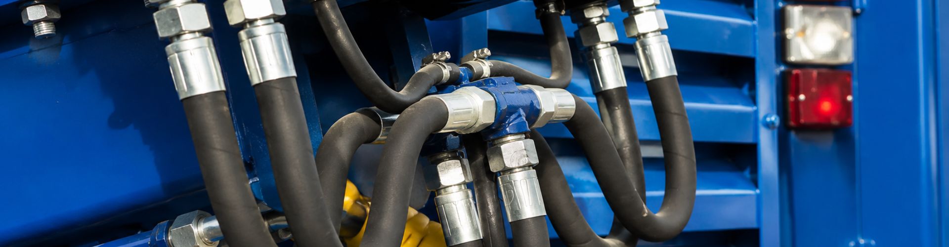
When a hose assembly needs one special Parker 43 end,

When someone requests one urgent Parker fitting, the fastest safe
“1-inch flange” is not enough information to recommend a Parker
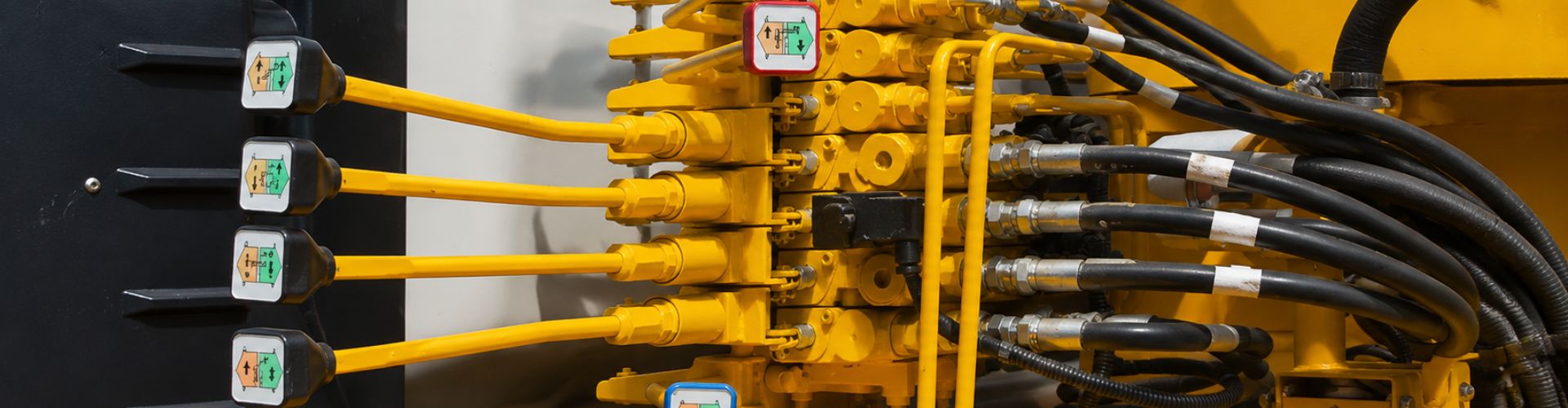
A Parker 13943 fitting replacement can be technically acceptable at

External leakage releases oil outside the cylinder, while internal leakage
Choose the hose by calculating the inside diameter from maximum

Before approving a Parker one-piece fitting replacement, verify the exact
Low MOQ hydraulic fittings can help a small repair shop